


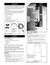

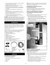
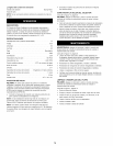

ATTACH INLET
Refer to Figure 7.
inlet needs to be attached to right side of dust collector
assembly. To attach inlet:
• Position inlet over 2W' hole on right side of dust collector
assembly.
• Secure inlet using four 4.2-1.4 x 12ram thread-forming
screws.
Figure 7 - Attaching Inlet
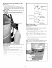
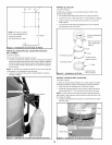
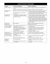
ATTACH HOSE
Refer to Figure 8.
Hose needs to be attached to the inlet using hose clamp.
To attach hose:
• Slide hose clamp onto one end of hose. Loosen clamp
screw if required to slide hose clamp onto hose.
• Position the hose clamp wires on the hose grooves.
• Slide hose with clamp onto inlet.
• Tighten hose clamp screw to secure hose with inlet.
• Slide other hose clamp onto the opposite hose end. This
end will be connected to the dust producing machine
Figure 8 - Attaching Hose
DANGER: Do not permit fingers to touch terminals of plug
when installing or removing the plug to or from the outlet.
WARNING: Do not connect to power source until unit is
completely assembled.
POWER SOURCE
• Motor is designed for operation on the voltage and fre-
quency specified on motor nameplate.
• Normal loads will be handled safely on voltages not more
than 10% above or below the specified voltage.
• Running unit on voltages not within range may cause over-
heating and motor burnout.
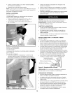
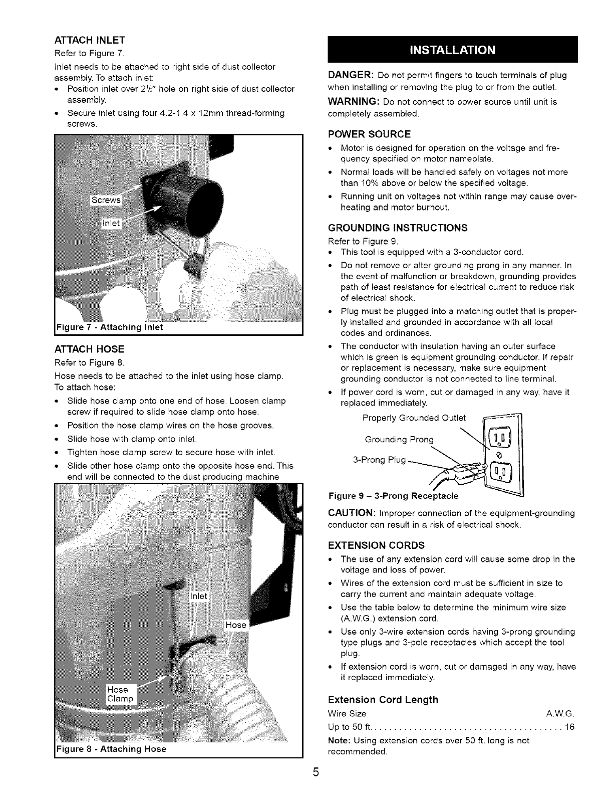
GROUNDING INSTRUCTIONS
Refer to Figure 9.
• This tool is equipped with a 3-conductor cord.
• Do not remove or alter grounding prong in any manner. In
the event of malfunction or breakdown, grounding provides
path of least resistance for electrical current to reduce risk
of electrical shock.
• Plug must be plugged into a matching outlet that is proper-
ly installed and grounded in accordance with all local
codes and ordinances.
• The conductor with insulation having an outer surface
which is green is equipment grounding conductor. If repair
or replacement is necessary, make sure equipment
grounding conductor is not connected to line terminal.
• If power cord is worn, cut or damaged in any way, have it
replaced immediately.
Properly Grounded Outlet
Grounding Prong
3-Prong Plug @I__
Figure 9 - 3-Prong Receptacle
CAUTION: improper connection of the equipment-grounding
conductor can result in a risk of electrical shock.
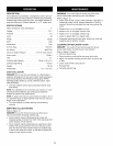
EXTENSION CORDS
• The use of any extension cord will cause some drop in the
voltage and loss of power.
• Wires of the extension cord must be sufficient in size to
carry the current and maintain adequate voltage.
• Use the table below to determine the minimum wire size
(A.W.G.) extension cord.
• Use only 3-wire extension cords having 3-prong grounding
type plugs and 3-pole receptacles which accept the tool
plug.
• If extension cord is worn, cut or damaged in any way, have
it replaced immediately.
Extension Cord Length
Wire Size A.W.G.
Up to 50 ft....................................... 16
Note: Using extension cords over 50 ft. long is not
recommended.