


11
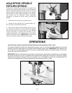
Fig. 21
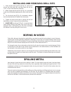
Fig. 22
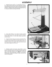
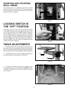
4. Fig. 21, illustrates the table alignment pin (B)
removed. Loosen table locking bolt (D) Fig. 21, tilt table
to the desired angle and tighten bolt (D). When returning
table to the level position, replace table alignment pin
(B). This will automatically position the table surface at
90 degrees to the spindle.
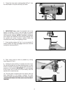
5. A tilt scale (E) and pointer (F) Fig. 22, are provided
on the table bracket casting to indicate the degree of tilt.
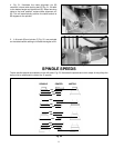
SPINDLE SPEEDS
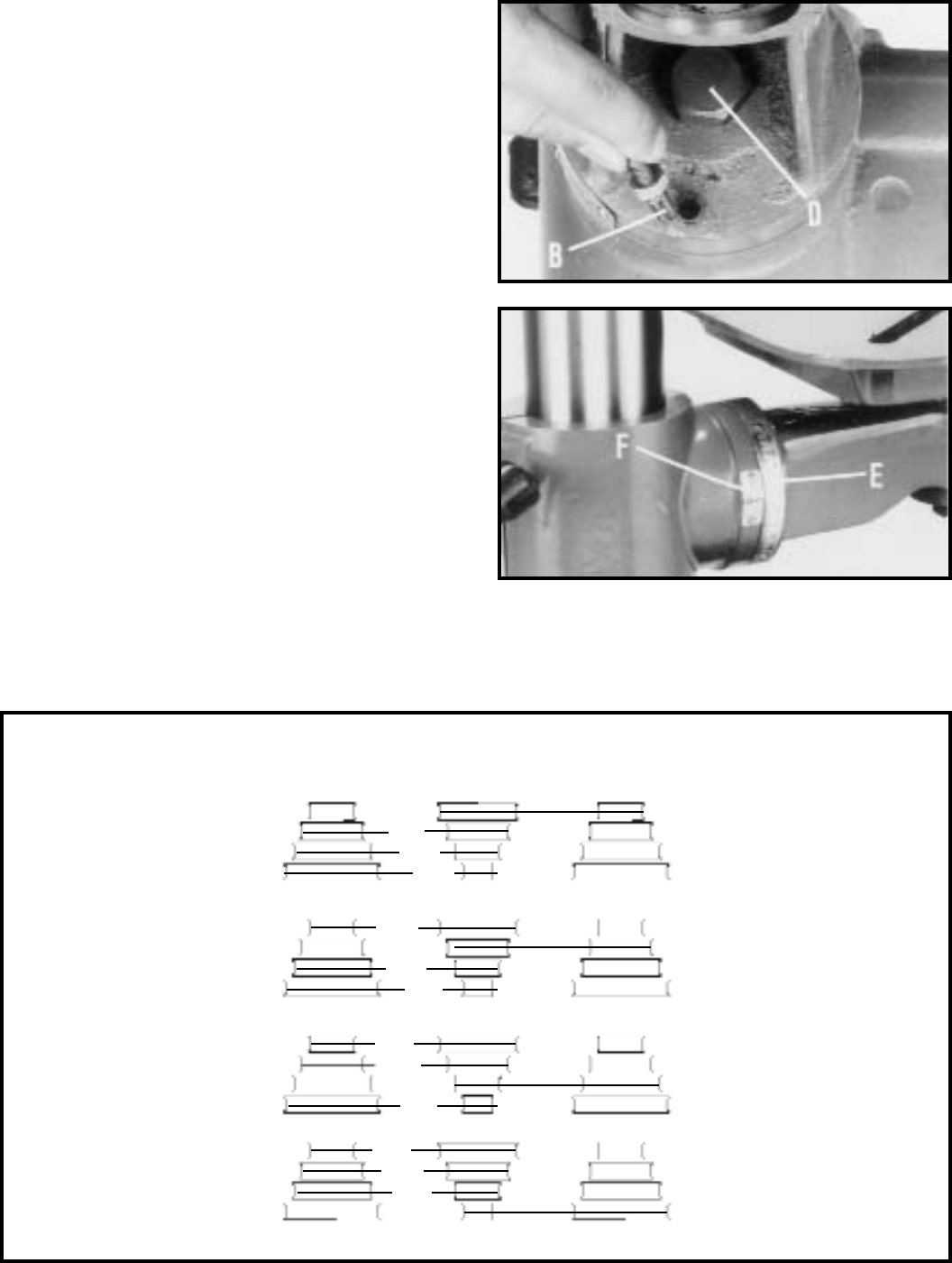
Twelve spindle speeds are available on the drill press. Fig. 23, illustrates the speeds and which steps of the pulleys the
belts must be positioned to obtain the 12 speeds.
Fig. 23
SPINDLE
CENTER
MOTOR
540
360
250
1090
590
410
1820
1280
650
3000
2180
1450