


12
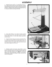
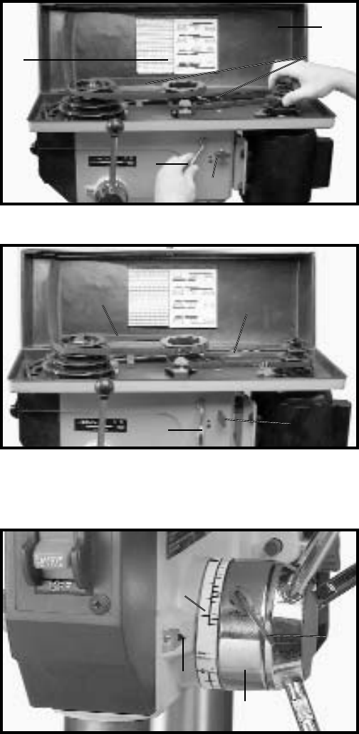
Fig. 26
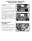
DRILLING HOLES
TO DEPTH
When a number of holes are to be drilled to exactly the
same depth, a depth stop is provided in the pinion shaft
housing and is used as follows:
1. Loosen lock screw (A) Fig. 26, and rotate housing (B)
until the pointer (C) lines up with the desired depth
indicated on scale (D). Then tighten lock screw (A).
2. All holes will then be drilled to the exact depth as
indicated on scale (D) Fig. 26. NOTE: Scale (D) is
calibrated in both inches and millimeters.
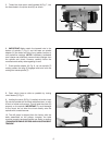
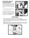
Fig. 24
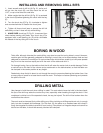
Fig. 25
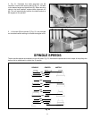
CHANGING SPINDLE SPEEDS AND
ADJUSTING BELT TENSION
1. DISCONNECT THE DRILL PRESS FROM THE
POWER SOURCE.
2. Raise the belt and pulley guard (A) Fig. 24.
3. Release tension on the belt by loosening lock knob
(B) Fig. 24, and the tension knob located on the other
side of the head casting and moving tension lever (C)
forward.
4. Position both belts (D) Fig. 24, on the desired steps
of the spindle, center, and motor pulleys as shown.
Refer to chart (E) Fig. 24, which is conveniently located
on the underside of the belt and pulley guard (A) for belt
position and speed charts.
5. After the belts are positioned on the desired steps of
the spindle, center, and motor pulleys, move tension
lever (C) Fig. 25, to the rear until the belts are properly
tensioned and tighten two tension lock knobs (B), one of
which is shown. NOTE: The belts should be just tight
enough to prevent slipping. Excessive tension will
reduce the life of the belt, pulleys, and bearings. Correct
tension is obtained when the belts (D) can be flexed
approximately one inch at the center of the pulleys using
light finger pressure.
A
C
B
E
D
C
B
D
D
A
B
C
D