


6
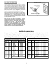
Fig. 7
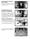
Fig. 8
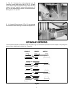
Fig. 9
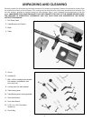
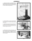
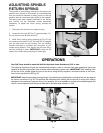
5. Thread the three pinion shaft handles (N) Fig. 7, into
the three holes in the pinion shaft (P) as shown.
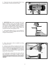
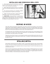
6. IMPORTANT: Make certain the tapered hole in the
bottom of spindle (T) Fig. 8, and the taper on spindle
adapter (U) are clean and free of any grease, lacquer or
rust preventive coatings. NOTE: If necessary, household
oven cleaner can effectively remove these coatings from
the spindle and chuck; however, carefully follow the
manufacturer’s safety rules regarding its use.
7. Push spindle adapter (U) Fig. 8, up into spindle (T)
making certain the tang (V) engages and locks with the
mating slot inside spindle (T).
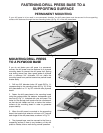
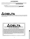
8. Open chuck jaws as wide as possible by turning
chuck sleeve (T) Fig. 9.
9. Holding the chuck (S) Fig. 9, carefully drive the chuck
(S) onto the spindle with a rubber mallet as shown, or with
a block of wood and hammer. This will seat the chuck (S)
properly on the spindle. IMPORTANT: To avoid damage
to the chuck, do not drive the chuck directly onto the
spindle with a metal hammer.
10. The drill press is shipped from the factory with the
belts assembled on the pulleys; however, the belts
must be properly tensioned before use. Refer to section
“CHANGING SPINDLE SPEEDS AND ADJUSTING BELT
TENSION”.
N
N
P
T
S
T
U
V