


10
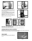
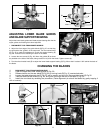
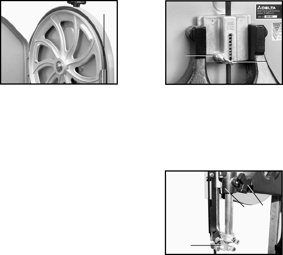
ADJUSTING THE UPPER BLADE GUIDES AND BLADE SUPPORT BEARING
Adjust the upper blade guides and blade support bearings ONLY AFTER the blade has the correct tension and is tracking
properly. To adjust, do the following:
1. DISCONNECT TOOL FROM POWER SOURCE
2. Make sure that the bottom blade guides and support bearings are clear of the blade.
3. Check the upper blade guide assembly. The blade guides (A) Fig. 27 should be parallel to the blade. To adjust, loosen the
screw (B) and rotate the complete guide assembly (C). When the blade guides are parallel with the blade, tighten the screw (B).
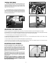
4. Adjust the guides (A) Fig. 28 so that the front edge of the guides are just behind the “gullets” of the saw teeth. The com-
plete guide block bracket can be moved in or out by loosening the thumb screw (C) and turning the knurled knob (D) Fig. 28.
When the guides (A) are set properly, tighten thumb screw (C).
5. Two set screws (B) Fig. 28 hold the upper blade guides (A) in place. Loosen the set screws (B) to move the guides (A). Place
them as close as possible to the side of the blade. (Be careful not to pinch the blade). Tighten the screws (B).
6. The upper blade support bearing (E) Fig. 28 prevents damage to the set in the saw teeth by keeping the blade from being
pushed too far toward the back. The support bearing (E) should be set 1/64" behind the blade by loosening the thumb screw
(F) and turning the knurled knob (G) to move the support bearing (E) in or out.
7. Adjust the blade support bearing (E) so that the back edge of the blade overlaps the outside diameter of the ball bearing by
about 1/16". The bearing (E) is set on an eccentric. To change the position, remove the screw (H) and bearing (E) Fig. 28.
Loosen the thumb screw (F), back out the knurled knob from the set screw. Remove the hex shaft from the hole, and rotate it
to move the eccentric for the bearing.
8. When the blade guide wears to a point that it cannot be adjusted close to the blade, loosen screw (B) Fig. 28 and reverse
the blade guides (A) Fig. 28.
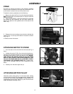
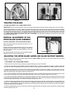
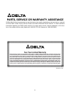
TRACKING THE BLADE
CAUTION: DISCONNECT TOOL FROM POWER SOURCE.
IMPORTANT: Before tracking the blade, make sure that the blade guides and blade support bearings are clear of the blade.
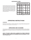
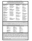
After applying tension to the blade, rotate the wheels slowly forward by hand and observe the blade’s movement. The blade
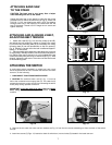
(A) Fig. 24 should travel in the center of the upper tire. If the blade creeps toward the front edge, loosen the wing nut (B) Fig.
25, and tighten the thumb screw (C). This action draws the blade toward the center of the tire. If the blade creeps toward the
back edge, turn the thumb screw in the opposite direction. Adjust the thumb screw (C) Fig. 25 only a fraction of a turn each
time. NEVER TRACK THE BLADE WHILE THE TOOL IS RUNNING. After the blade is tracking in the center of the tires, tight-
en the wing nut (B) Fig. 25.
VERTICAL ADJUSTMENT OF THE
UPPER BLADE GUIDE ASSEMBLY
CAUTION: DISCONNECT TOOL FROM POWER SOURCE.
Adjust the blade guides and bearings according to the fol-
lowing instructions.
Set the upper blade guide assembly (A) Fig. 26 as close as
possible to the top surface of the workpiece. Loosen the
lock knob (B) and move the guide assembly (A) to the
desired position.
If the guide assembly moves when lock knob (B) is loosened,
tighten set screw (C) until movement stops.
Fig. 24
Fig. 25
Fig. 26
A
B
C
A
B
C