


14
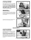
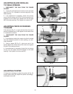
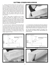
1. There are several methods that can be used to cut
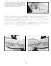
crown mouldings on the miter saw. The method shown
in Fig. 35, illustrates the contact surfaces (the surfaces
that contact the wall and ceiling) of the crown moulding
held firmly against the fence and table of the miter saw.
This method is acceptable when making a small number
of cuts but would not be practical for a production appli-
cation as it may be difficult to firmly hold the work in this
position. Also, this method means that the crown
moulding must be positioned on the table in the upside
down position.
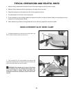
2. When a large number of repetitive cuts of crown
moulding are required we suggest the use of filler
blocks, as shown in Fig. 36 through Fig. 39. The majori-
ty of crown mouldings have contact surfaces at 52 and
38 degrees to the rear surface of the moulding and these
angles must be utilized when jointing the face of the filler
block. For crown mouldings with different angles, appro-
priate filler blocks can be produced.
3. Fig. 36 and Fig. 37, illustrate the filler block fastened
to the miter saw fence with the face of the filler block
extending outward from the top of the fence and down
to the surface of the table. When the filler block is posi-
tioned in this manner, the crown moulding must be posi-
tioned on the table in the upside down position. This
means that the surface of moulding that contacts the
ceiling is against the table.
Fig. 35
Fig. 37
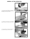
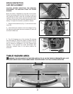
Fig. 38
Fig. 39
Fig. 36
4. Fig. 38 and Fig. 39, illustrate the filler block fastened
to the miter saw fence with the face of the filler block
extending inward toward the fence from the top to the
bottom. When the filler block is positioned in this man-
ner, the crown moulding is placed on the table in the
same position as it would be when nailed between the
ceiling and wall.
CUTTING CROWN MOULDINGS
FILLER BLOCK FOR CROWN MOULDING IF JOINT IS TO HAVE MITERED
CORNER FIT OR COPE CUT
FILLER BLOCK FOR CROWN MOULDING IF JOINT IS TO HAVE MITERED
CORNER FIT OR COPE CUT