


10
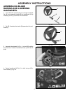
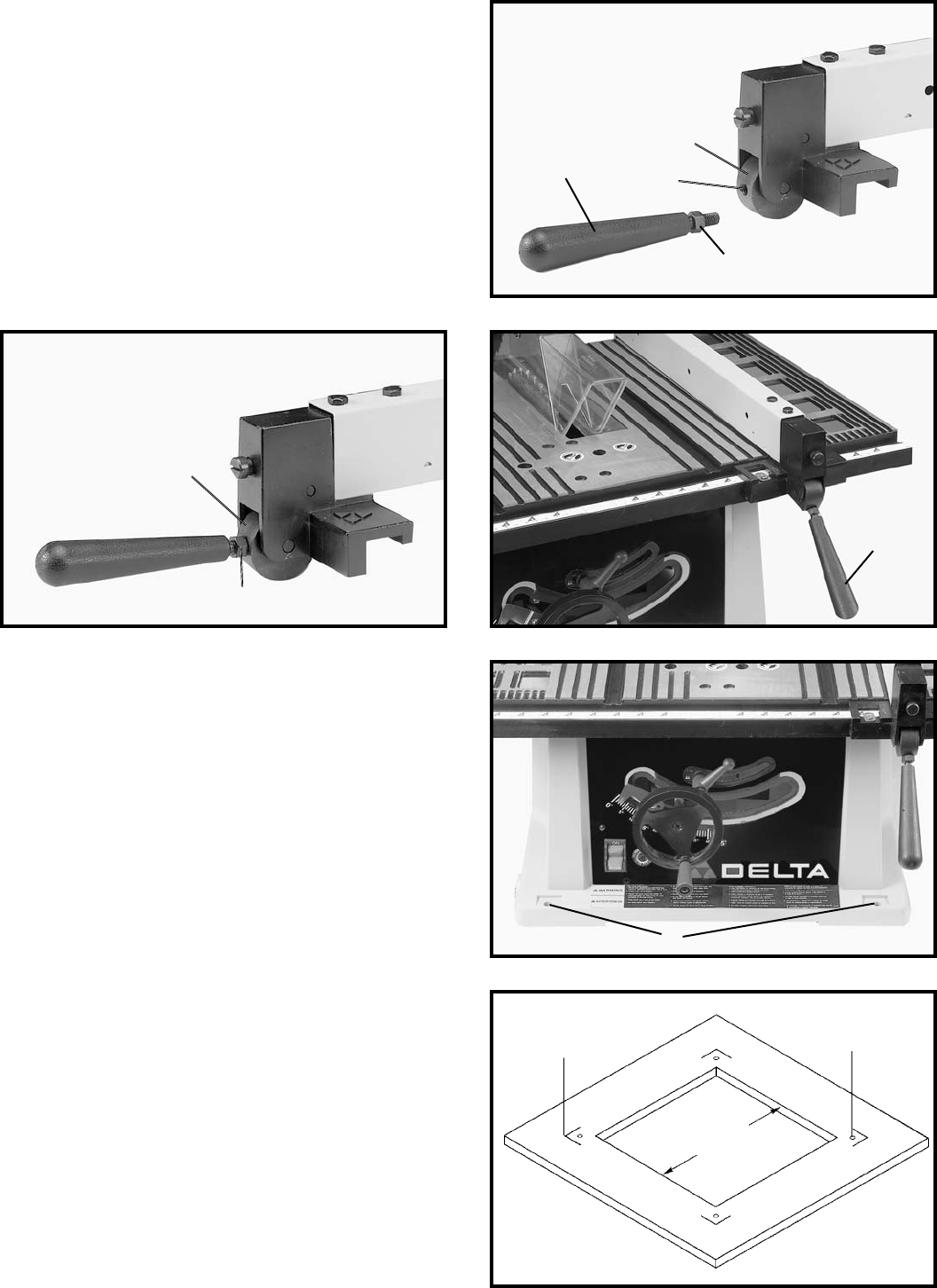
Fig. 17
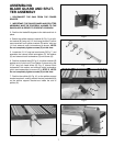
Fig. 18AFig. 18
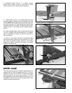
Fig.19
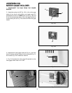
Fig. 20
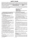
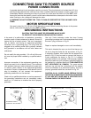
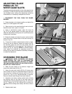
The saw MUST be properly secured to a supporting sur-
face using the four mounting holes, two of which are
shown at (A) Fig. 19.
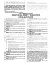
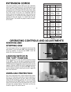
IMPORTANT: A HOLE MUST BE PROVIDED IN THE
SUPPORTING SURFACE TO FACILITATE SAWDUST
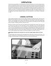
FALL-THRU AND REMOVAL. Square the saw on the
supporting surface and mark the location of the four 5/16
inch holes to be drilled, as shown in Fig. 20. Locate and
mark an 11 or 12 inch square centered between the four
mounting holes and cut out and remove the square, as
shown in Fig. 20. This opening will allow sawdust to fall
through the saw base. Fasten the saw to the workbench
utilizing the mounting holes that were just drilled.
IMPORTANT: FAILURE TO PROVIDE THIS SAW DUST
FALL-THRU AND REMOVAL HOLE WILL ALLOW SAW
DUST TO BUILD-UP AROUND THE MOTOR WHICH
MAY RESULT IN A FIRE HAZARD OR CAUSE MOTOR
DAMAGE.
FASTENING SAW TO A
SUPPORTING SURFACE
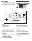
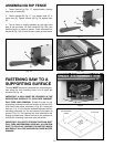
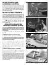
ASSEMBLING RIP FENCE
1. Thread locknut (A) Fig. 17, approximately halfway
onto stud of handle (B).
2. Thread handle (B) Fig. 17, into tapped hole (C) in
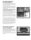
fence cam (D). Tighten locknut (A) Fig. 18, against cam
(D).
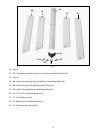
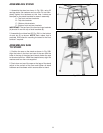
3. The rip fence is usually operated on the right hand
side of the saw table. Lift lock handle (B) Fig. 18A, and
position fence on table as shown. Push downward on
handle (B) Fig. 18A, to lock fence in place on saw table.
SAW PLACEMENT
MARKS
5/16" HOLES
11" OR 12"
SQUARE
CUTOUT
B
A
D
C
D
A
B
A