


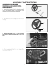
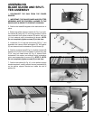
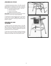
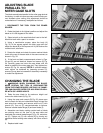
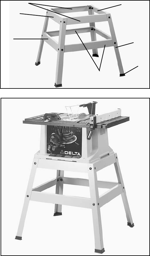
ASSEMBLING STAND
1. Assemble the stand as shown in Fig. 20A, using 32
carriage bolts, flat washers and hex nuts. Do not com-
pletely tighten the hardware at this time. Letters are
stamped on the stand brackets for ease in assembly.
A - Top front and rear brackets
B - Top side brackets
C - Bottom side brackets
D - Bottom front and rear brackets
IMPORTANT: The top lips of the front and rear brackets
(A) should fit over the top of side brackets (B).
2. Assemble the rubber feet (E) Fig. 20A, to the bottom
of each leg (F) as shown. NOTE: Each rubber foot is
provided with holes for mounting the stand to the floor
surface if required.
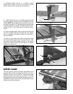
ASSEMBLING SAW
TO STAND
1. Position the saw on the stand as shown in Fig. 20B.
Align the holes in the front and rear of the saw with the
holes in the top of the stand and loosely fasten the saw
to the stand with four 16MM hex head screws, eight flat
washers and four hex nuts supplied
2. Push down on top of the saw so the legs of the stand
adjust to the surface of the floor and tighten all stand
hardware and hardware which secures saw to stand.
Fig. 20A
Fig. 20B
B
A
B
C
F
E
D
11