


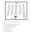
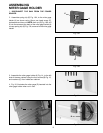
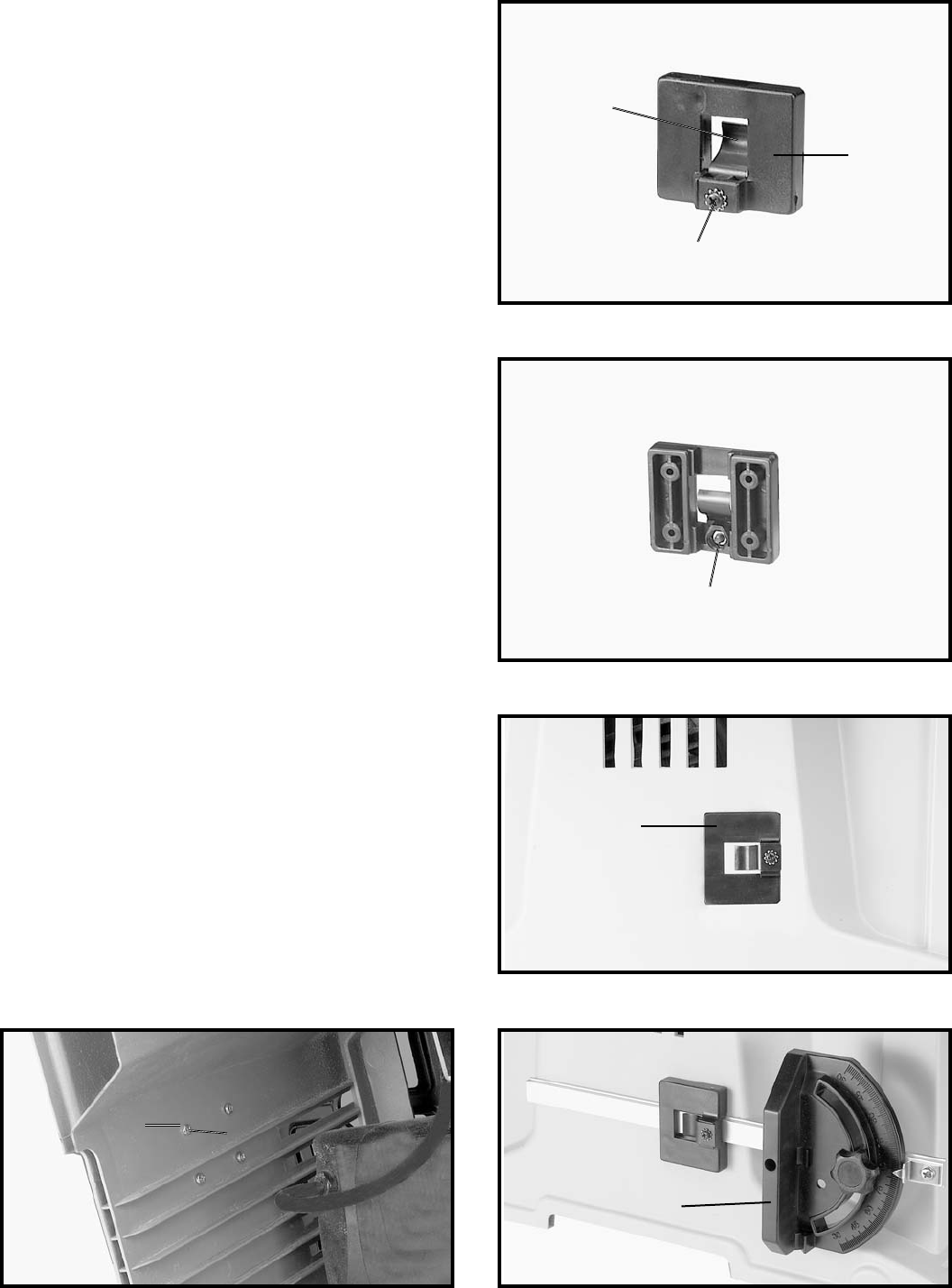
Fig. 13A
Fig. 13B
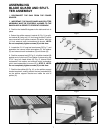
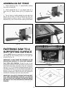
Fig. 14
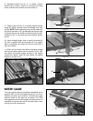
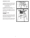
Fig. 15 Fig. 16
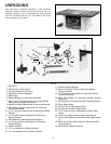
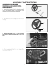
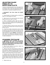
ASSEMBLING
MITER GAGE HOLDER
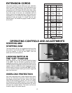
1. DISCONNECT THE SAW FROM THE POWER
SOURCE.
2. Assemble spring clip (E) Fig. 13A, to the miter gage
holder (A) as shown using 10mm pan head screw (F),
lockwasher and hex nut. NOTE: Hex nut (G) Fig. 13B, will
fit into the recess at the back of the miter gage holder (A)
to keep spring clip (E) Fig. 13A, secured to the miter gage
holder.
3. Assemble the miter gage holder (A) Fig. 14, to the left
side of the saw cabinet using the four screws (B) Fig. 15,
and washers (C) from inside saw cabinet.
4. Fig. 16, illustrates the miter gage (D) inserted into the
miter gage holder when not in use.
E
A
F
G
A
B
C
D
9