


11
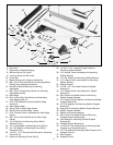
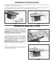
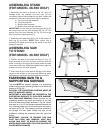
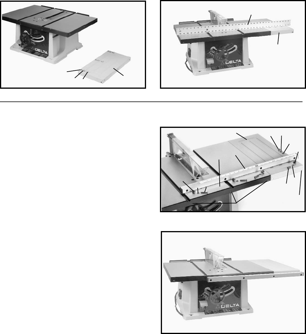
ASSEMBLING EXTENSION WING
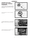
1. Assemble extension wing (A) Fig. 18, to the saw table using three 1/4-20 x 5/8” hex head screws (B), 1/4"
lockwashers (C), and 1/4" flat washers (D).
2. With a straight edge (E) Fig. 19, make certain the top, front and rear edges of the extension wing (A) are level with
the saw table before tightening three screws which secure extension wing to saw table.
Fig. 18 Fig. 19
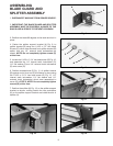
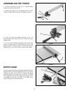
ASSEMBLING GUIDE RAIL TO SAW
1. Loosely fasten guide rail (A) Fig. 20, to three threaded
holes (B) in saw table (C) using three 1/4-20 x 1-1/4"
long screws (D), 1/4" lockwashers (E), and spacers (F).
IMPORTANT: Spacers (F) Fig. 20, are positioned
between guide rail (A) and saw table (C).
2. Fasten guide rail (A) Fig. 20, to extension wing (G)
through hole (K) using the 1/4-20 x 1-1/4” long screw
(D), 1/4" lockwasher (E), spacer (F), 1/4" flat washer (H),
1/4" lockwasher (E), and 1/4-20 hex nut (J). Then tighten
all guide rail mounting hardware.
IMPORTANT: Spacers (F) Fig. 20, are positioned
between guide rail (A) and extension wing (G).
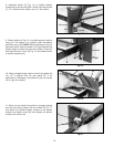
3. Fig. 21, illustrates the guide rail properly assembled to
saw table and extension wing.
Fig. 20
Fig. 21
E
A
A
B
C
D
F
E
D
C
A
G
J
E
H
D
E
K
F
B