


18
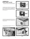
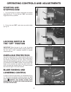
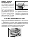
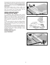
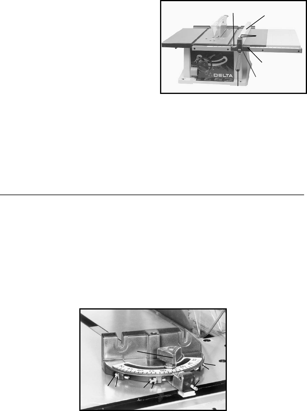
RIP FENCE OPERATION
AND ADJUSTMENTS
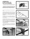
1. To move the rip fence (A) Fig. 48, along the table, lift
up fence locking lever (B), slide the fence to the desired
location on the table and push down fence locking lever
(B) to lock the fence in position.
2. A pointer is supplied to indicate the distance the
fence is positioned away from the saw blade. If an
adjustment to the pointer is required, loosen the screw
(C) Fig. 48, that fastens the pointer to the fence bracket
and adjust the pointer accordingly. Then, tighten screw
(C).
3. IMPORTANT: THE RIP FENCE MUST BE
PROPERLY ALIGNED TO THE MITER GAGE SLOT IN
ORDER TO PREVENT KICKBACK WHEN RIPPING.
4. The saw blade is set parallel to the miter gage slot at
the factory and the fence must be parallel to the miter
gage slot in order to do accurate work and prevent
kickback when ripping. To check the alignment:
5. Position the fence at one end of the miter gage slot,
as shown in Fig. 48. Clamp the fence to the table by
pushing down the locking lever (B). The edge of the
fence should then line up parallel with the miter gage
slot.
6. If an adjustment is necessary, proceed as follows:
Fig.48
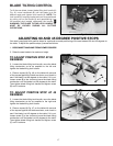
MITER GAGE OPERATION AND ADJUSTMENTS
When straight cross-cutting (blade set 90 degrees to the table) the miter gage can be used in either table slot. When
bevel cross-cutting (blade tilted) only use the miter gage in the right table slot where the blade is tilted away from the
miter gage and your hands.
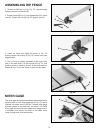
This miter gage is equipped with individually adjustable index stops at 90 degrees and 45 degrees right and left.
Adjustment to the index stops can be made by loosening lock nuts (B) Fig. 49, and tightening or loosening the three
adjusting screws (C) until they contact the other end of stop pin (D) when the miter gage is at 90 and 45 degrees to the
saw blade. Then, tighten lock nuts (B).
To operate the miter gage, simply loosen lock knob (E) Fig. 49, and move the body of the miter gage to
the desired angle. When the stop pin (D) is pushed in, the miter gage body will stop at 90 degrees and
45 degrees right and left. To rotate the miter gage body past these points, pull out stop pin (D).
Fig.49
7. Loosen the two screws (D) Fig. 48, and lift up locking
lever (B). Then while holding the fence bracket (F) firmly
toward the front of the saw, move the rear end of the
fence (A) until it is parallel with the miter gage slot. Then
tighten two screws (D) and push down locking lever (B).
8. The clamping action of the fence (A) Fig. 48, can be
adjusted by lifting up locking lever (B) and turning screw
(E) clockwise to increase or counterclockwise to
decrease the clamping action of the fence.
C
B
C
B
C
B
D
E
C
A
D
F
E
B