


15
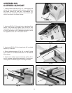
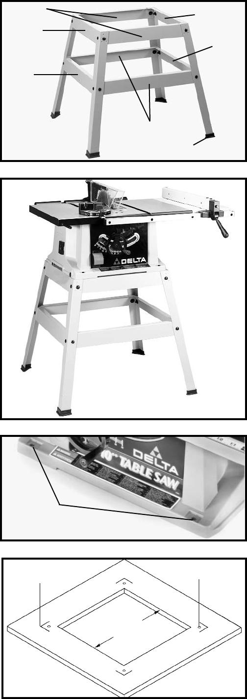
ASSEMBLING STAND
(FOR MODEL 36-560 ONLY)
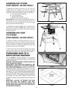
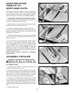
1. Assemble the stand as shown in Fig. 36, using 16
carriage bolts, flat washers and hex nuts. Do not
completely tighten the hardware at this time. Letters are
stamped on the stand brackets for ease in assembly.
A - Top front and rear brackets
B - Top side brackets
C - Bottom side brackets
D - Bottom front and rear brackets
IMPORTANT: The top front and rear brackets (A) Fig. 36,
are longer than the top side brackets (B) Fig. 36. The
bottom front and rear brackets (D) Fig. 36, are longer
than the bottom side brackets (C).
2. Assemble the rubber feet (E) Fig. 36, to the bottom of
each leg (F) as shown. NOTE: Each rubber foot is
provided with holes for mounting the stand to the floor
surface if required.
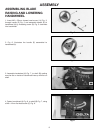
ASSEMBLING SAW
TO STAND
(FOR MODEL 36-560 ONLY)
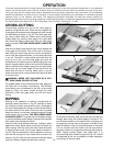
1. Position the saw on the stand as shown in Fig. 37.
Align the holes in the front and rear of the saw with the
holes in the top of the stand and loosely fasten the saw
to the stand with four 16MM hex head screws, eight flat
washers and four hex nuts supplied
2. Push down on top of the saw so the legs of the stand
adjust to the surface of the floor and tighten all stand
hardware and hardware which secures saw to stand.
Fig. 36
Fig. 37
A
B
B
C
C
D
E
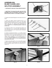
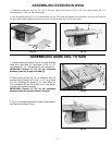
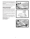
FASTENING SAW TO A
SUPPORTING SURFACE
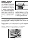
The saw MUST be properly secured to a supporting
surface using the four mounting holes, two of which are
shown at (A) Fig. 38.
CAUTION: THE SUPPORTING SURFACE MUST BE
ABLE TO SUPPORT 300LBS.
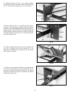
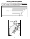
IMPORTANT: A HOLE MUST BE PROVIDED IN THE
SUPPORTING SURFACE TO FACILITATE SAWDUST
FALL-THRU AND REMOVAL. Square the saw on the
supporting surface and mark the location of the four
5/16 inch holes to be drilled, as shown in Fig. 39. Locate
and mark an 11 or 12 inch square centered between the
four mounting holes and cut out and remove the square,
as shown in Fig. 39. This opening will allow sawdust to
fall through the saw base. Fasten the saw to the
workbench utilizing the mounting holes that were just
drilled.
IMPORTANT: FAILURE TO PROVIDE THIS SAW
DUST FALL-THRU AND REMOVAL HOLE WILL
ALLOW SAW DUST TO BUILD-UP AROUND THE
MOTOR WHICH MAY RESULT IN A FIRE HAZARD OR
CAUSE MOTOR DAMAGE.
Fig. 38
A
Fig. 39
SAW PLACEMENT
MARKS
5/16" HOLES
11" OR 12"
SQUARE
CUTOUT