


18
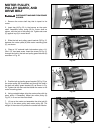
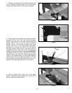
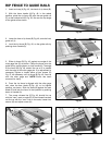
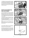
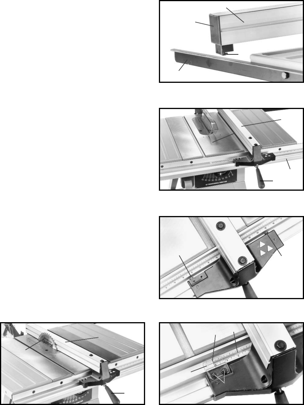
3. Lower the front of rip fence (B) Fig. 46, onto the front
guide rail (L).
4. Lock the rip fence (B) Fig. 46, on the guide rails by
pushing down handle (A).
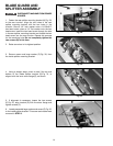
RIP FENCE TO GUIDE RAILS
1. Insert end cap (A) Fig. 45, into back of rip fence (B).
2. With the fence handle (A) Fig. 46, in the raised
position, place the rip fence (B) onto the rear guide rail
(C) so the hooked end (D) Fig. 45, fits over the top ledge
of the guide rail as shown.
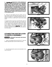
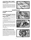
5. Slide rip fence (B) Fig. 46, against one edge of the
miter gage slot (C) as shown. Clamp the fence onto the
guide rail by pushing down on lock handle (A). The edge
of the fence (B) Fig. 46, should line up so it is parallel
with the edge of the miter gage slot. If an adjustment is
necessary, tighten or loosen either of two screws (D)
Fig. 47, as necessary until rip fence (B) Fig. 46, lines up
with the miter gage slot. NOTE: Cursor has been
removed for clarity.
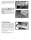
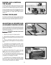
6. Once the rip fence is aligned with the miter gage
slot, raise the saw blade (E) Fig. 48, to its highest
position, as shown. Slide rip fence (B) against the saw
blade (E) and lock the fence in that position by pushing
down on handle (A).
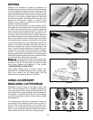
7. The cursor witness line (F) Fig. 49, should line up
with the “zero” mark on scale (G). If the witness line does
not line up with the “zero” line on the scale, loosen two
screws (H) and adjust cursor (K).
Fig. 45
B
A
C
D
Fig. 46
B
C
A
L
Fig. 47
D
D
Fig. 48 Fig. 49
A
B
E
H
K
F
G