13
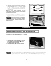
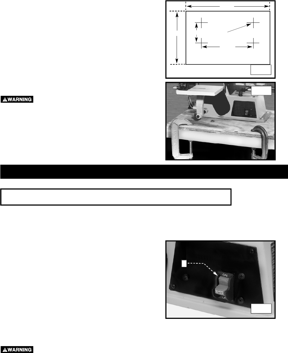
3. Alternately, you can secure the sander by fastening it
to a mounting board 18" x 24" or larger. The diagram
in Fig. 16 shows the size and center-to-center
distance of the holes that you will need to drill in the
mounting board.
N O T E : For proper stability, countersink the holes
underneath the mounting board so that the screw heads
are flush with bottom surface.
4. Securely clamp the mounting board to a stand or
workbench using 2 or more “‘C” clamps, as shown in
Fig. 17.
Secure the machine base to the supporting
surface. If there is any tendency for the stand or workbench
to move during operation, the stand or workbench must be
fastened to the floor.
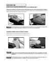
1. The on/off switch (A) Fig. 18 is located on the front
of the sander. To turn the machine “ON”, move
the switch up to the “ON” position.
2. To turn the machine “OFF”, move the switch (A)
down to the “OFF” position.
O P E R AT I O N
O P E R AT I O N A L CONTROLS AND ADJUSTMENTS
Make sure that the switch is in the “OFF” position before plugging in the power cord. In the event of
a power failure, move the switch to the “OFF” position. An accidental start-up can cause injury.
A
STARTING AND STOPPING THE SANDER
Fig. 16
Fig. 17
Fig. 18
l l
l l
18 MIN
5-1/2"
15-1/2"
24 MIN
3/8" DIAMETER
(4) HOLES


