


7
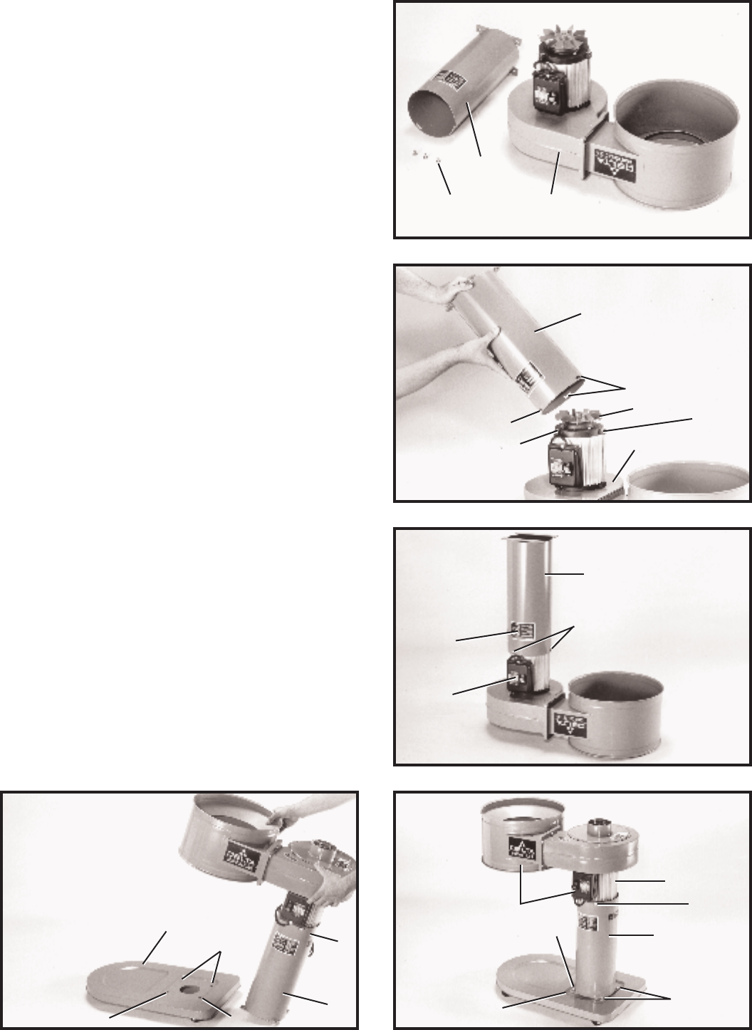
ASSEMBLING
SUPPORT TUBE A N D
MOTO R AND BLOWER
ASSEMBLY TO BASE
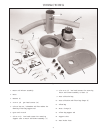
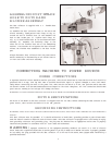
1. Place the motor and blower assembly (A) Fig. 5,
upside down on a sturdy supporting surface.
2. Find the support tube (B) Fig. 5, and three 1/2 inch-
long hex head screws (C).
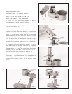
3. Carefully place support tube (B) Fig. 6, over the moto r
impellers (D). Align three holes (E) Fig. 6, in support tube
(B) with three holes in the motor casting, two of which are
shown at (F) and fasten support tube (B) to motor and
blower assembly (A) with three 1/2 inch-long screws
(C) Fig. 7. Warning label (K) Fig. 7, should be positioned
over the on/of f switch (L) when support tube (B) is prop -
erly positioned as shown. NOTE: Do not tighten three
screws, two of which are shown at (C) Fig. 8, at this time.
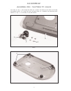
4. Carefully turn motor and blower assembly (A) Fig. 8,
with support tube (B) att ached, right side up. Align the
four holes in the feet of support tube (B) Fig. 8, with four
threaded holes (K) in base and fasten motor and blower
assembly (A) Fig. 9, to base (L) with four 5/16-18 x 1/2
hex head screws, three of which are shown at (M).
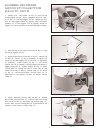
5. IMPORTANT:Make certain motor and blower assem-
bly (A) Fig. 9, is p arallel with base (L). If adjustment is
necessary, rotate motor (N) on support tube (B) and
tighten three mounting screws, one of which is shown
at (C).
Fig. 5
Fig. 6
Fig. 7
Fig. 9Fig. 8
C
B
A
B
E
E
D
F
A
C
K
L
K
K
K
L
A
B
N
C
B
M
M
L
A
F
B