


7
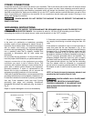
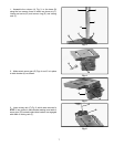
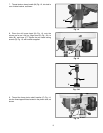
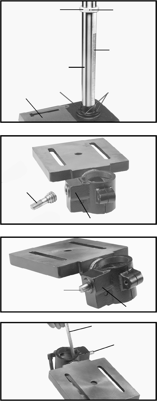
1. Assemble the column (A) Fig. 3, to the base (B)
using the four screws, three of which are shown at (C).
Loosen set screw (D) and remove ring (E) and raising
rack (F).
Fig. 3
Fig. 4
Fig. 5
G
H
H
G
Fig. 6
F
G
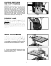
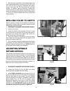
2. Make certain worm gear (G) Figs. 4 and 5, is in place
in table bracket (H) as shown.
3. Insert raising rack (F) Fig. 6, which was removed in
STEP 1, into groove in table bracket making sure teeth of
worm gear (G) located inside table bracket are engaged
with teeth of raising rack (F).
E
D
F
A
B
C
C