


8
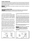
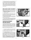
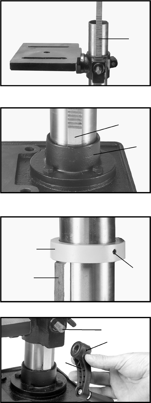
Fig. 7
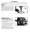
Fig. 8
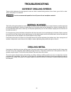
Fig. 9
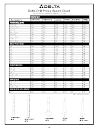
Fig. 10
G
K
L
F
F
J
D
E
F
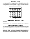
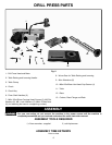
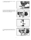
4. Slide raising rack (F) Fig. 7, table and table bracket
onto drill press column, as shown. Make sure bottom of
raising rack (F) Fig. 8, is inside the flange (J) on drill
press base.
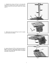
5 . Re-assemble ring (E) Fig. 9, which was removed in
S T E P 1. I M P O R TA N T: Bottom of ring (E) MUST NOT b e
pushed all the way down onto top of raising rack (F). M A K E
S U R E top of raising rack (F) is under bottom of ring (E) and
that there is enough clearance to allow rack (F) to rotate
around the column. THEN TIGHTEN SET SCREW (D)
BEING CAREFUL NOT TO OVERTIGHTEN.
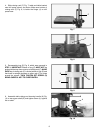
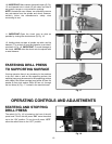
6. Assemble table raising and lowering handle (K) Fig.
10, to worm gear shaft (G) and tighten screw (L) against
flat on shaft.