


13
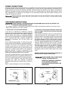
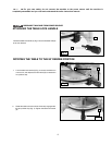
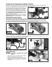
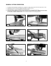
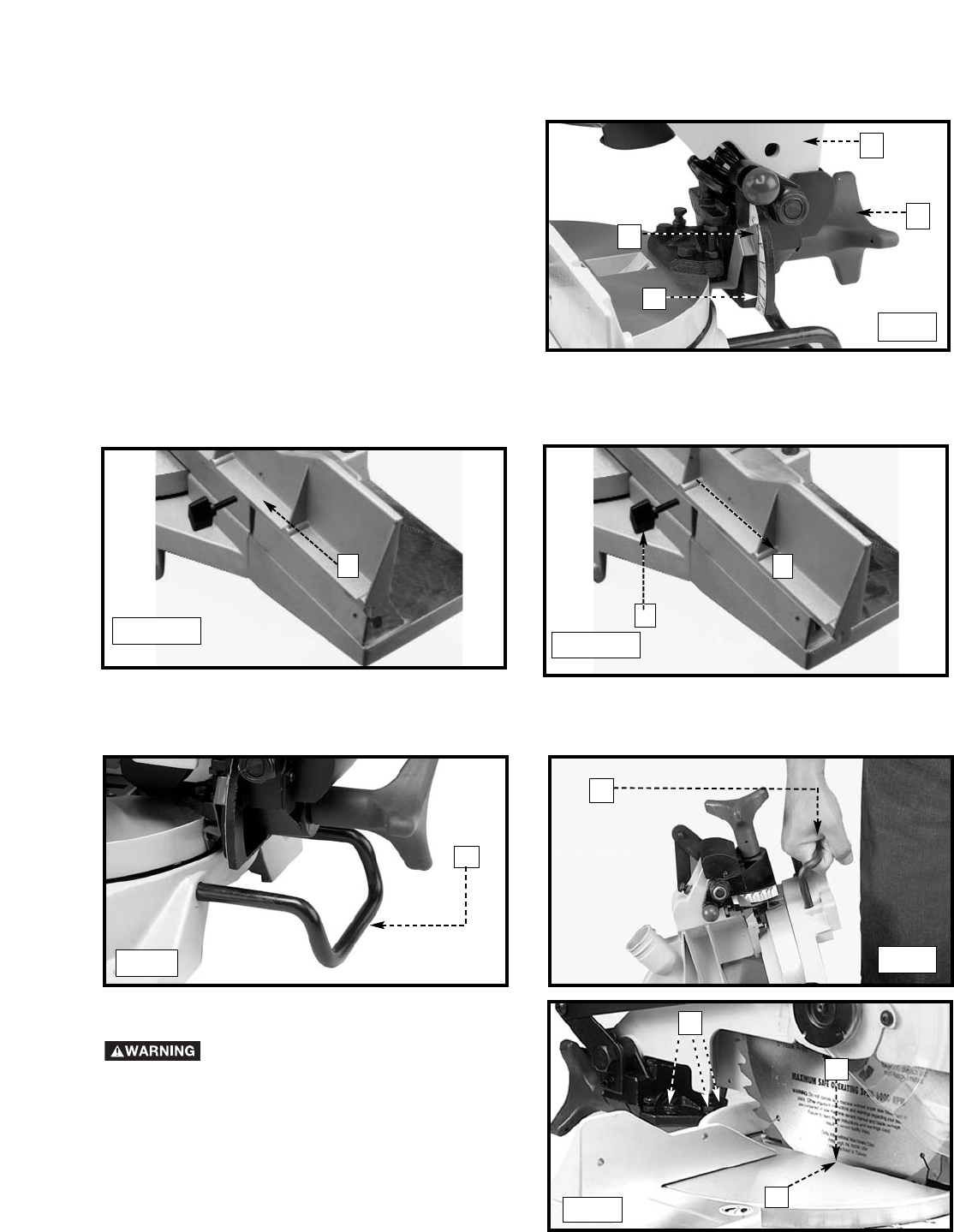
You can tilt the cuttinghead of your compound miter saw to cut
any bevel angle from a 90° straight cut off to a 45° left bevel
angle. Loosen the bevel lock handle (A) Fig. 18, tilt the cutting
arm (B) to the desired angle, and tighten the lock handle (A).
Positive stops are provided to rapidly position the saw blade at
90° and 45° to the table. Refer to the section of this manual
titled “ADJUSTING 90° AND 45° BEVEL STOPS.” The bevel
angle of the cuttinghead is determined by the position of the
pointer (C) Fig.18 on the scale (D).
A triangle indicator is provided on the bevel scale at the 33.86°
bevel angle for cutting crown moulding. Refer to the “CUTTING
CROWN MOULDING” section of this manual.
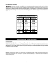
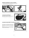
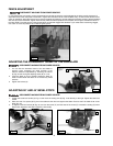
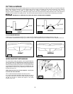
A rear support bar (A) Fig. 19 is provided to prevent the machine from tipping to the rear when the cuttinghead returns to the up
position. For maximum support, pull the bar (A) out as far as possible.
You can also use the support bar (A) Fig. 20 to carry the machine.
TILTING THE CUTTINGHEAD FOR BEVEL CUTTING
C
B
A
D
Fig. 18
REAR SUPPORT/CARRYING HANDLE
A
Fig. 19
Fig. 20
A
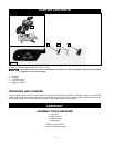
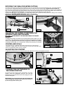
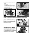
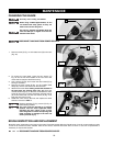
ADJUSTING THE BLADE PARALLEL TO
THE TABLE SLOT
1. Lower the cutting arm. The saw blade (A) Fig. 21 should be
parallel to the left edge (B) of the table opening.
2. To adjust, loosen the three bolts (C) Fig. 21 and move the
cutting arm until the blade is parallel with the left edge (B)
of the table opening and centered in the slot. Tighten the
three bolts (C).
DISCONNECT MACHINE FROM POWER
SOURCE!
Fig. 21
C
B
A
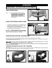
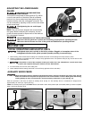
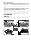
IMPORTANT: Move the sliding fence to provide clearance for the blade and guard. The degree of tilt determines
how far to move the sliding fence. Refer to the section “Adjusting Sliding Fence”.
The sliding fence (A) Fig. 18A provides support for extra large workpieces used with your saw. Set it as close as
possible to the saw blade. When miter cutting (blade 90° to the table and at an angle to the right or left), set the
fence all the way toward the blade (Fig. 18B). When bevel cutting, however (blade tilted at an angle to the table),
move the fence (A) far enough away from the blade to allow for proper clearance. To reposition the fence, loosen the
lock handle (B), and slide the fence (A) to the desired location. Tighten the lock handle (B).
ADJUSTING SLIDING FENCE
Fig. 18A
A
A
B
Fig. 18B