


14
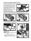
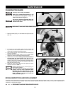
1. Loosen the bevel lock handle (A) Fig. 18 and move the cutting arm (B) Fig. 19 all the way to the right. Tighten the bevel lock
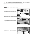
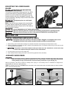
handle.
2. Place one end of a square (A) Fig. 24 on the table and the other end against the blade. Check to see if the blade is 90° to the
table (Fig. 24).
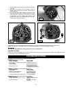
3. To adjust, loosen the locknut (B) Fig. 25, and turn the screw (C) until the head of the screw (C) contacts the casting (D) when
blade is 90° degrees to the table. Tighten the locknut (B).
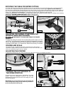
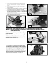
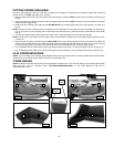
1. You can limit the downward travel of the saw blade to
prevent it from contacting any metal surfaces of the
machine. Make this adjustment by loosening the locknut
(A) Fig. 23 and turning the adjusting screw (B) in or out.
2. Lower the blade as far as possible. Rotate the blade by
hand to make certain the teeth do not contact any metal
surfaces.
3. Tighten the locknut (A)
ADJUSTING THE DOWNWARD TRAVEL OF THE SAW BLADE
DISCONNECT MACHINE FROM POWER SOURCE!
Fig. 23
ADJUSTING 90° AND 45° BEVEL STOPS
DISCONNECT MACHINE FROM POWER SOURCE!
A
B
Fig. 24
Fig. 25
A
D
C
B
Fig. 22
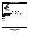
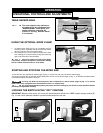
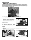
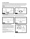
In order that the saw can bevel to a full 47 degrees left, the left side of the fence can be adjusted to the left to provide clearance. To
adjust the fence, loosen the plastic knob shown in Figure 22 and slide the fence to the left. Make a dry run with the saw turned off and
check for clearance. Adjust the fence to be as close to the blade as practical to provide maximum workpiece support, without interfering
with arm up & down movement. Tighten knob securely. When the bevel operations are complete, don’t forget to relocate the fence to
the right. NOTE: The guide groove in the left side fence can become clogged with sawdust. If you notice that it is becoming clogged,
use a stick or some low pressure air to clear the guide groove.
FENCE ADJUSTMENT
DISCONNECT MACHINE FROM POWER SOURCE!