


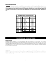

15
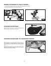
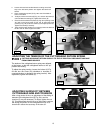
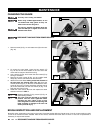
4. Loosen the bevel lock handle. Move the cutting arm all the
way to the left bevel position and tighten the bevel lock
handle.
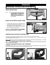
5. Use a combination square (A) Fig. 26 to see if the blade is
at 45° to the table.
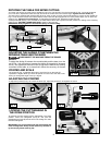
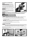
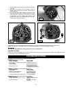
6. To adjust, loosen the locknut (E) Fig. 27, and turn the screw (F)
until it contacts the casting (G). Tighten the locknut (E).
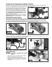
7. Check to see that the bevel pointer (P) Fig. 28 is pointing to the
45° mark on the bevel scale (S) Fig. 26. To adjust the bevel
pointer (P) Fig. 28, loosen the screw (H) and adjust pointer (P).
Tighten the screw (H) securely.
8. These positive stops enable you to rapidly position the blade at
the 90° and 45° bevel angle to the table.
A
S
Fig. 26
Fig. 27
Fig. 28
E
G
F
P
H
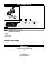
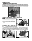
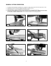
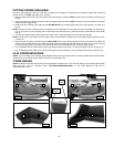
The tension of the cuttinghead return spring was adjusted
at the factory so that the cuttinghead returns to the "up"
position after cutting.
To adjust the spring tension, loosen the locknut (A) Fig.
29 and turn the screw (B) (clockwise to increase or
counterclockwise to decrease the spring tension). After
adjustment, tighten the locknut (A).
ADJUSTING THE TENSION OF THE CUTTINGHEAD RETURN SPRING
CUTTING HEAD MUST RETURN QUICKLY TO THE UP POSITION. DISCONNECT MACHINE
FROM POWER SOURCE.
B
A
Fig. 29
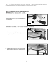
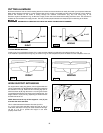
After a long period of time, an adjustment of the sliding fit
between the cuttinghead arm (B) Fig. 29A, and the
trunnion (C) may be necessary. To adjust, tighten the nut
(D). This adjustment should not be so tight that it restricts
the sliding movement of the cuttinghead arm (B) or so
loose that it affects the accuracy of the saw cut.
ADJUSTING SLIDING FIT BETWEEN
CUTTINGHEAD ARM AND TRUNNION
C
D
Fig. 29A
B