


12
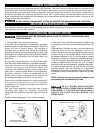
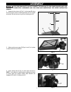
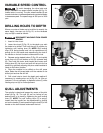
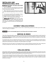
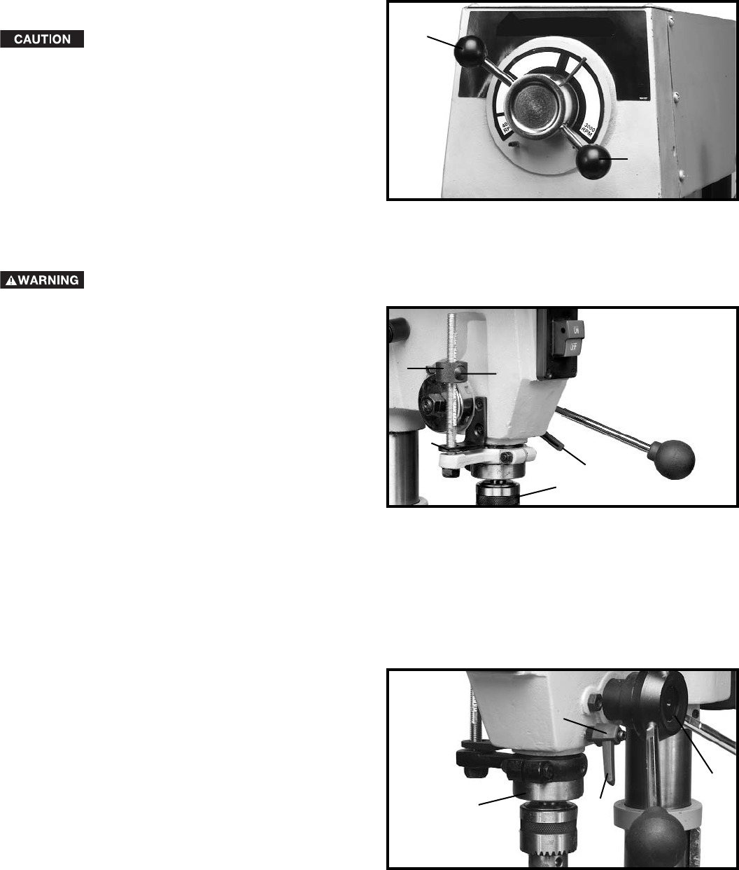
VARIABLE SPEED CONTROL
To avoid damaging the drive belts and
pulleys, DO NOT turn speed control handles (A) Fig. 24,
unless motor is running. The pilot wheel handles (A) are
turned clockwise to increase speed and counterclockwise
to decrease speed. The speed range is 500 rpm to 3100
rpm.
Fig. 24
A
A
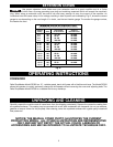
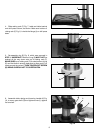
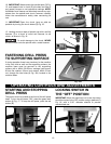
DRILLING HOLES TO DEPTH
Where a number of holes are to be drilled to exactly the
same depth, the stop nut (A) Fig. 25, on the threaded
stop rod (B) is used as follows:
DISCONNECT MACHINE FROM POWER
SOURCE.
1. Insert bit into chuck.
2. Lower the chuck (C) Fig. 25, to the depth you wish
the holes to be drilled. Then lock the quill in position by
tightening quill locking lever (E). NOTE: Quill locking
lever (E) is spring-loaded and can be repositioned by
pulling out on the handle and repositioning the hub of
the handle on the bolt located underneath the hub.
3. Depress spring-loaded button (F) Fig. 25, and rapidly
move stop nut (A) until bottom of nut (A) contacts stop
(G). Then hold the pinion shaft handle and loosen quill
locking lever (E), the chuck and quill will return to the up
position by gradually allowing the pinon shaft handles to
rotate to the return position.
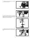
4. Place the material to be drilled on the drill press
table. Raise the drill press table until the material to be
drilled just touches the drill bit.
5. Drill a test hole to check the depth and readjust if
necessary by rotating stop nut (A) Fig. 25, for fine ad-
justment. It is not necessary to depress button (F) while
rotating stop nut (A) for fine adjustment.
Fig. 25
A
C
E
F
G
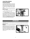
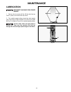
QUILL ADJUSTMENTS
The spindle is raised and lowered by means of the pilot
wheel (A) Fig. 26. The quill (B) can be locked at any
desired point in its travel by tightening the quill locking
lever (C). NOTE: The quill locking lever (C) is spring-
loaded and the handle can be repositioned by pulling
out on the handle (C) and repositioning the hub (D) of the
handle on the bolt located underneath the hub.
Fig. 26
A
B
C
D