


6
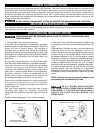
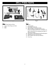
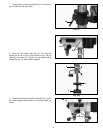
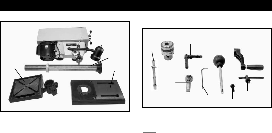
DRILL PRESS PARTS
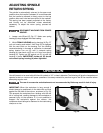
Fig. 1
Fig. 1
1 - Drill Press Head and Motor
2 - Column, Base Flange, and Rack
3 - Table
4 - Base
Fig. 2
5 - Chuck
6 - Clamp Handle
7 - Pinon Shaft Handles (3)
8 - Table Raising and Lowering Handle
9 - M8x1.25x125mm Carriage Head Screws (2),
8.5mm Flat Washers (2), 8.5mm Lock Washers (2),
M8x1.25 Hex Nuts (2), (for fastening the base to a
supporting surface)
10 - Worm Gear for Table Raising and Lowering Mechanism
11 - Wrenches (one 3mm and one 5mm)
12 - M8x1.25x25mm Hex Head Cap Screws (4)
13 - Chuck Key
1
2
6
3
4
7
5
13
11
10
8
12
Fig. 2
9