


15
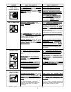
MAINTENANCE
Belt - Replacement
SERIOUS INJURY OR DAMAGE MAY OC-
CUR IF PARTS OF THE BODY OR LOOSE
ITEMS GET CAUGHT IN MOVING PARTS.
NEVER OPERATE THE OUTFIT WITH THE
BELT GUARD REMOVED. THE BELT GUARD
SHOULD BE REMOVED ONLY AFTER THE
SPARK PLUG WIRE HAS BEEN DISCON-
NECTED.
To replace belt:
1. Disconnect spark plug wire.
2. Remove belt guard.
3. Loosen four engine mounting screws, two saddle/
stiffener plate screws, handle set screw, and
stiffener bar nut on engine and slide engine toward
compressor.
4. Remove belt and replace with new.
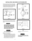
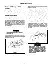
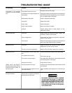
5. Push the engine back into regular position. Achieve
belt tension by inserting a large screwdriver into the
hole in the saddle which is located on the belt guard
side of the saddle below the engine and prying the
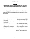
stiffener plate back. See Figure 8. Proper tension is
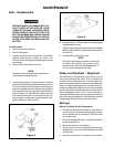
approximately 1/4" belt deflection measured mid-
way between the pulley and flywheel when a 3-
pound weight or equivalent finger pressure is ap-
plied at this point. See Figure 9.
NOTE
The belt must be centered over the grooves on
the flywheel and engine pulley.
Figure 8
Before You Store The Air Compressor:
1. Review the "Operating Procedures" and "Mainte-
nance" sections on the preceding pages and per-
form maintenance as necessary. Drain the water
from the air tank.
2. Review the Briggs & Stratton "Operating and Main-
tenance Instructions".
3. Remove the air tool or accessory.
4. Protect the air hose from damage (such as being
stepped on or run over). Wind it loosely around the
outfit handle.
5. Store the compressor in a clean and dry location.
Figure 9
6. Hold belt tension until two engine mounting screws
are tightened securely.
7. Tighten remaining engine mounting screws, saddle/
stiffener plate screws, handle set screw and stiff-
ener bar nut.
8. Reinstall belt guard and screws.
NOTE
Once the engine pulley has been moved from
its factory set location, the grooves of the
flywheel and pulley must be aligned within 1/
16" to prevent excessive belt wear.
The compressor flywheel and motor pulley must be
inline (in the same plane) within 1/16" to assure belt
retention within sheave grooves. To check alignment,
disconnect spark plug wire and remove the beltguard.
Place a straight edge against the outside of the fly-
wheel and measure the distance from it to the nearest
groove. Alignment is achieved when the other end of
the straightedge is within 1/16" of the measured di-
mension at the pulley grooves. Squareness is achieved
when the pulley grooves are an equal distance from the
straightedge on both sides of the motor shaft.
Pulley and Flywheel - Alignment
Storage