


8
ASSEMBLY INSTRUCTIONS
Installing Handle, Foot Extension
Bracket, Wheels, Outlet Valve
THE WHEELS AND HANDLE DO NOT PRO-
VIDE ADEQUATE CLEARANCE, STABILITY
OR SUPPORT FOR PULLING THE UNIT UP
AND DOWN STAIRS OR STEPS. THE UNIT
MUST BE LIFTED OR PUSHED UP A RAMP.
Do not use the engine gas tank as a support
for lifting the air compressor.
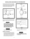
1. Insert the handle into pockets under the tank
saddle. Put one set screw through hole in one side
of tank saddle and tighten down on handle.
It may be necessary to brace or support one
end of the outfit when attaching the wheels
and the foot extension bracket because the
air compressor will have a tendency to tip
before both wheels are assembled.
Items Needed for Assembly
• 20 oz. of oil for the engine (see Briggs & Stratton
instructions). Use 10W30 high quality motor oil.
• 16 oz. of compressor oil, SAE 20-20W, non-deter-
gent, low foaming.
• a 9/16" socket or open-end wrench for attaching the
wheels.
• a 7/16" open-end wrench for attaching the foot
extension bracket and rubber feet.
• a 1/4" open-end wrench to tighten handle set
screw.
• an adjustable wrench for attaching the shut-off
valve and air outlet adapter.
EXCESSIVE TANK VIBRATION CAN WEAK-
EN THE AIR TANK AND CAUSE RUPTURE
OR EXPLOSION. RUBBER FEET MUST BE
INSTALLED.
2. Attach the rubber feet to the bottom of the foot
extension bracket. Attach foot extension bracket to
the air tank bracket. Use one cap screw, one lock
washer, and one hex nut at each end. Tighten.
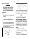
3. The leg bracket on the underside of the air com-
pressor tank has 2 holes on each side for mounting
the wheels. Place one shoulder bolt through the
hole in a wheel. Next, push the bolt through the
LOWER hole of the leg bracket and screw on one
hex locking nut. The special locking nut does not
turn freely. Tighten the nut firmly until it contacts the
tank leg. See separate Parts Manual. The outfit will
sit level if the wheels are properly installed.
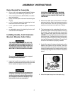
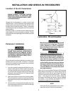
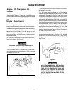
4. Apply teflon tape to the tapered pipe threads on the
adapter and tighten into the manifold. Install the
swivel connection end of the shut-off valve to the
straight threaded end of the adapter (teflon tape is
not required) and tighten this connection. See photo
below.
5. Attach the spark plug wire to the spark plug.
ADAPTER
SHUT-OFF
VALVE
MANIFOLD
SWIVEL
CONNECTION