


6
Operate the air compressor in a clean, dry and well ventilated area.
The air intake filter must be kept clear of obstructions which could
reduce air delivery of the air compressor. The air compressor should
be located at least 12" away from walls or other obstructions that
could interfere with the flow of air through the fan bladed flywheel.
The air compressor crankcase and head are designed with fins to
provide proper cooling.
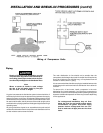
The flywheel side of the outfit should be placed toward the wall and
protected with a totally enclosed belt guard. In no case should the
flywheel be closer than 12 to 18 inches from the wall or other
obstruction that will interfere with the flow of air through the fan
bladed flywheel. The area should allow space on all sides for air
circulation and for ease of normal maintenance. Keep the outfit away
from areas which have dirt, vapor, and volatile fumes in the atmo-
sphere which may clog and gum the intake filter and valves, causing
inefficient operation.
If humidity is high, an air filter can be installed in line to remove
excessive moisture. Closely follow instructions packaged with the
filter for proper installation. It must be installed as close as possible
to the accessory.
The air compressor should be as near to air outlets as possible in
order to avoid long pipe lines. Do not place the air compressor where
heat is excessive.
Do not use an extension cord. To avoid voltage drop and power loss
to the motor, use extra air hose instead of an extension cord.
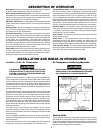
Anchoring of Vertical Unit
INSTALLATION AND BREAK-IN PROCEDURES
THE MANIFOLD ASSEMBLY DOES NOT PROVIDE
ADEQUATE STABILITY OR SUPPORT FOR LIFTING
THE UNIT. IF THE OUTFIT MUST BE MOVED, USE
THE TANK FOR LIFTING.
VIBRATION CAN WEAKEN THE AIR TANK AND CAUSE
AN EXPLOSION. THE COMPRESSOR MUST BE PROP-
ERLY MOUNTED AS ILLUSTRATED BELOW.
Air Compressor Anchoring Methods
Location of the Air Compressor
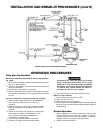
DESCRIPTION OF OPERATION
Drain Valve: The drain valve is located at the base of the air tank and
is used to drain condensation at the end of each use.
Motor Thermal Overload Protector: The electric motor has an
automatic thermal overload protector. If the motor overheats for any
reason, the thermal overload protector will shut off the motor. The
motor must be allowed to cool before restarting.
ON/AUTO - OFF Switch: Turn this switch ON to provide automatic
power to the pressure switch and OFF to remove power at the end
of each use.
Air Intake Filter: This filter is designed to clean air coming into the
pump. This filter must always be clean and ventilation openings free
from obstructions. See "Maintenance".
Air Compressor Pump: To compress air, the pistons moves up and
down in the cylinder. On the downstroke, air is drawn in through the
air intake valves. The exhaust valve remains closed. On the upstroke
of the piston, air is compressed. The intake valves close and
compressed air is forced out through the exhaust valve, through the
outlet tube, through the check valve and into the air tank. Working
air is not available until the compressor has raised the air tank
pressure above that required at the air outlet.
Check Valve: When the air compressor is operating, the check valve
is “open”, allowing compressed air to enter the air tank. When the
air compressor reaches “cut-out” pressure, the check valve “closes”,
allowing air pressure to remain inside the air tank.
Pressure Release Valve: The pressure release valve located on the
side of the pressure switch, is designed to automatically release
compressed air from the compressor head and the outlet tube when
the air compressor reaches “cut-out” pressure or is shut off. If the
air is not released, the motor will try to start, but will be unable to. The
pressure release valve allows the motor to restart freely. When the
motor stops running, air will be heard escaping from the valve for a
few seconds. No air should be heard leaking when the motor is
running, or continuous leaking after unit reaches cut-out pressure.
Pressure Switch: The pressure switch automatically starts the
motor when the air tank pressure drops below the factory set “cut-
in” pressure. It stops the motor when the air tank pressure reaches
the factory set “cut-out” pressure.
Shut-off Valve: Turn the knob counterclockwise to open the valve
and clockwise to close.
Safety Valve: If the pressure switch does not shut off the air
compressor at its cut-out pressure setting, the safety valve will
protect against high pressure by “popping out” at its factory set
pressure (slightly higher than the pressure switch cut-out setting).
Tank Pressure Gauge: The tank pressure gauge indicates the
reserve air pressure in the tank. On outfits with no pressure regulator,
this is also the pressure available at the air outlet.
Vertical Units
This compressor should be permanently mounted in place on a level
floor.Vertical air compressors must be bolted to the floor. Bolting
holes are provided in the base feet. Mount the air compressor on a
solid, level foundation. Support compressor weight evenly on all four
feet. Solid shims may be used if necessary.