


8
Piping
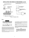
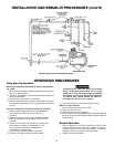
A typical compressed air distribution system below should be of
sufficient pipe size to keep the pressure drop between the supply
and point of use to a minimum. All pipes and fittings used must be
certified safe for the pressures involved. Pipe thread lubricant must
be used on all threads, and all joints are to be made up tight, since
small leaks in the piping system are the largest single cause of high
operating costs.
All piping should be sloped to an accessible drain point and all
outlets should be taken from the top of the main distribution air line
so that moisture cannot enter the outlet.
The main distribution air line should not be smaller than the
compressor air discharge valve outlet. A smaller line will restrict the
flow of air. If piping is over 100 feet long, or if required air flow will
exceed 15 SCFM, use 3/4" piping.
It is recommended that a flexible coupling be installed between the
air discharge valve outlet and main air distribution line to allow for
vibration.
To remove dirt, oil and water, install a separator in the main
distribution line. Install separator 5 to 6 feet from compressor to
allow the air to cool to room temperature before passing through the
separator. Additional separators or filters may be used depending
on the application.
Note
For underground installation, bury air lines
below the frost line and avoid pockets where
condensation can gather and freeze. Apply
pressure before underground lines are cov-
ered to make sure all pipe joints are free from
leak
s.
Plastic or PVC pipe is not designed for use with
compressed air. Regardless of its indicated pres-
sure rating, plastic pipe can burst from air pres-
sure. Use only metal pipe for air distribution lines.
Note
Where a remote air intake is used, enlarge
the size of the air intake piping by one pipe
size for each 10 feet of length.
INSTALLATION AND BREAK-IN PROCEDURES (cont'd)
Wiring of Compressor Units