


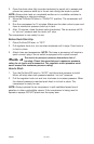

Assembly for “Horizontal” units
Tools Required for Assembly
1 - 9/16” socket or open end wrench
1 - 3/8” socket or open end wrench
1 - 1/2” socket or open end wrench
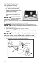
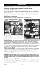
1. (if equipped) To make installation easier, submerge handle grip into warm
soapy water. Remove handle
grip from soapy water and
slide onto handle.
2. Insert the handle inside the
compressor saddle and line up
the two bolt holes on each
side.
3. Install the four screws, two on
each side.
4. Tighten securely.
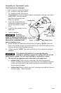
It will be
necessary to
brace or support one side of the
outfit when installing the wheels
because the compressor will
have a tendency to tip.
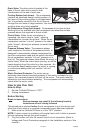
5. Attach wheels with shoulder bolts and nuts as shown. NOTE: Place the
bolts in the bottom hole of the wheel bracket on units 20-29 gallons and in
the top hole on units 30 gallons and up.
6. Tighten securely. NOTE: The outfit will sit level if the wheels are properly
installed.
The wheels and handle do not provide adequate
clearance, stability or support for pulling the unit up and
down stairs or steps. The unit must be lifted, or pushed up a ramp.
7. The unit will be equipped with rubber feet or a rubber strip
a. (rubber strip) Clean and dry underside of air tank leg opposite
wheels. Remove the protective paper strip from the adhesive backed
rubber foot strip. Attach the rubber foot strip to the bottom of leg.
Press firmly into place.
b. (rubber feet) Attach rubber feet with the screws provided as shown in
previous figure. Tighten securely.
11- ENG
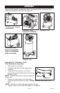
D26368
Rubber Feet
Screw
Nut
Wheel
Shoulder Bolt
Handle
Screw
Handle Grip
Rubber Strip