


English
11
Mounting and Using Depressed Center
Grinding Wheels and Sanding Flap Discs
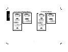
MOUNTING AND REMOVING HUBBED WHEELS
WARNING: To reduce the risk of serious personal injury,
turn tool off and disconnect tool from power source before
making any adjustments or removing/installing attachments
or accessories. Before reconnecting the tool, depress and
release the trigger switch to ensure that the tool is off.
Hubbed wheels install directly on the 5/8"-11 threaded spindle.
Thread of accessory must match thread of spindle.
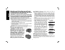
1. Backing flange is retained to the grinder by an O-ring on the
spindle. Remove backing flange by pulling and twisting flange
away form the machine.
2. Thread the wheel on the spindle by hand.
3. Depress the spindle lock button and use a wrench to tighten
the hub of the wheel.
4. Reverse the above procedure to remove the wheel.
CAUTION: Failure to properly seat the wheel before turning the
tool on may result in damage to the tool or the wheel.
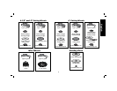
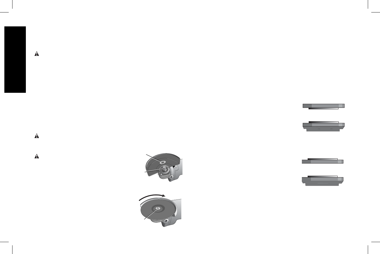
MOUNTING NON-HUBBED WHEELS
G1
N
WARNING: To reduce the risk of
serious personal injury, turn tool off and
disconnect tool from power source
before making any adjustments or
removing/installing attachments or
accessories. Before reconnecting the
tool, depress and release the trigger
switch to ensure that the tool is off.
F
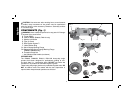
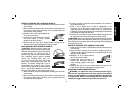
Depressed center Type 27 grinding wheels
must be used with included flanges.
NOTE: The stamped steel quick-change
backing flange (G2) is for use with D28065
and D28065N for Type 27 grinding wheels only. Refer to
pages 7-9 for more information.
1. Install the stamped steel quick-change backing flange (G2)
(D28065, D28065N only) for Type 27 6" wheels or the quick-
change backing flange (G1) for all other non-hubbed wheels
on spindle (N) with the raised section (pilot) against the wheel.
Be sure the backing flange recess is seated onto the flats of
the spindle by pushing and twisting the flange before placing
wheel.
2. Place wheel against the backing flange, centering the wheel on
the raised section (pilot) of the backing flange.
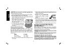
3. While depressing the spindle lock
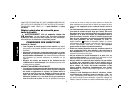
1/4" WHEELS
(6.35 mm)
Quick-Change
backing flange
threaded clamp nut
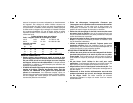
1/8" WHEELS
(3.17 mm)
threaded clamp nut
Quick-Change
backing flange
button, thread the clamp nut (H) on
spindle. If the wheel you are installing
is more than 1/8" (3.17 mm) thick,
place the threaded clamp nut on the
spindle so that the raised section (pilot)
fits into the center of the wheel. If the
wheel you are installing is 1/8"
(3.17 mm) thick or less, place the
threaded clamp nut on the spindle so
that the raised section (pilot) is not
against the wheel.
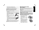
4. While depressing the spindle lock button,
tighten the clamp nut with a wrench.
5. To remove the wheel, depress the
spindle lock button and loosen the
threaded clamp nut with a wrench.
NOTE: If the wheel spins after the clamp
nut is tightened, check the orientation of
the threaded clamp nut. If a thin wheel is
installed with the pilot on the clamp nut against the wheel, it will
spin because the height of the pilot prevents the clamp nut from
holding the wheel.