


English
14
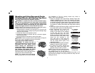
1. Thread the wheel on the spindle by hand.
2. Depress spindle lock button and use a wrench on the hub of
the wire wheel or brush to tighten the wheel.
3. To remove the wheel, reverse the above procedure.
CAUTION: Failure to properly seat the wheel hub before turning
the tool on may result in damage to tool or wheel.
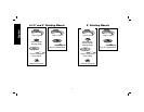
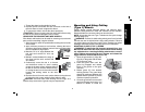
USING WIRE CUP BRUSHES AND WIRE WHEELS
Wire wheels and brushes can be used for removing rust, scale and
paint, and for smoothing irregular surfaces.
1. Allow the tool to reach full speed before touching the tool to the
work surface.
2. Apply minimum pressure to work surface, allowing the tool to
operate at high speed. Material removal rate is greatest when
the tool operates at high speed.
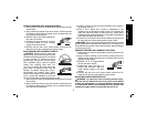
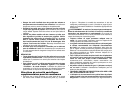
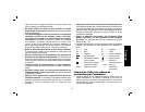
3. Maintain a 5˚ to 10˚ angle between the
5˚-10˚
tool and work surface for wire cup
brushes.
4. Maintain contact between the edge of
the wheel and the work surface with
wire wheels.
5. Continuously move the tool in a forward
and backward motion to avoid creating
gouges in the work surface. Allowing the tool
to rest on the work surface without moving,
or moving the tool in a circular motion causes
burning and swirling marks on the work
surface.
6. Remove the tool from the work surface before turning the tool
off. Allow the tool to stop rotating before setting it down.
CAUTION: Use extra care when working over an edge, as a
sudden sharp movement of grinder may be experienced.
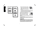
Mounting and Using Cutting
(Type 1) Wheels
Cutting wheels include diamond wheels and abrasive discs.
Abrasive cutting wheels for metal and concrete use are available.
Diamond blades for concrete cutting can also be used.
NOTE: All grinders that use Type 1 wheels use the quick-change
backing flange (G1).
WARNING: A closed, 2-sided cutting wheel guard is not included
with this tool and is re quired when using cutting wheels. Fail ure to
use proper flange and guard can re sult in injury resulting from wheel
breakage and wheel contact. See page 8 for more information.
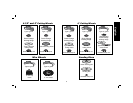
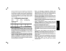
MOUNTING CLOSED (TYPE 1) GUARD
WARNING: To reduce the risk of serious personal injury, turn
tool off and disconnect tool from power source before making
any adjustments or removing/installing attachments or acces-
sories. Before reconnecting the tool, depress and release the
trigger switch to ensure that the tool is off.
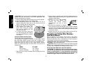
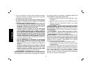
1. Open the guard latch (J). Align the
J
L
K
lugs (K) on the guard with the slots
(L) on the gear case.
2. Push the guard down until the
guard lug engages and rotates
freely in the groove on the gear
case hub.
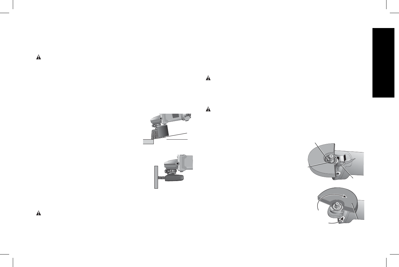
3. Rotate guard (D) into desired
working position. The guard body
D
should be positioned between the
spindle and the operator to provide
maximum operator protection.
4. Close the guard latch to secure the
guard on the gear case cover. You
should be unable to rotate the