


English
6
WARNING: Accessories must be rated for at least the speed
recom mended on the tool warning label. Wheels and other acces-
sories running over rated accessory speed may burst and cause
injury. Threaded accessories must have a 5/8"-11 hub. Every
unthreaded accessory must have a 7/8" (22.2 mm) arbor hole. If it
does not, it may have been designed for a circular saw and should
not be used. Use only the accessories shown on pages 7–9 of this
manual. Accessory ratings must be above listed minimum wheel
speed as shown on tool nameplate.
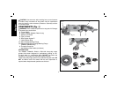
Mounting Guard
MOUNTING AND REMOVING GUARD
WARNING: To reduce the risk of serious personal injury,
turn tool off and disconnect tool from power source before
making any adjustments or removing/installing attachments
or accessories. Before reconnecting the tool, depress and
release the trigger switch to ensure that the tool is off.
CAUTION: Guards must be used with all grinding wheels, sand-
ing flap discs, wire brushes, and wire wheels. The tool may be used
without a guard only when sanding with conventional sanding discs.
Some D
EWALT models are provided with a guard intended for use
with depressed center wheels (Type 27) and hubbed grinding
wheels (Type 27). The same guard is designed for use with sanding
flap discs (Type 27 and 29) and wire brushes. Grinding and cutting
with wheels other than Type 27 and 29 require different accessory
guards not included with tool. Mounting instructions for these
accessory guards are included in the accessory package.
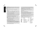
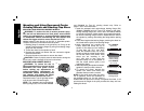
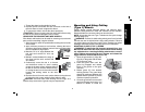
1. Open the guard latch (J). Align
J
L
K
the lugs (K) on the guard with the
slots (L) on the gear case.
2. Push the guard down until the
guard lugs engage and rotate
freely in the groove on the gear
case hub.
ASSEMBLY AND ADJUSTMENTS
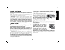
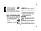
ATTACHING SIDE HANDLE
I
The side handle (I) can be fitted to either side of
the gear case in the threaded holes, as shown.
Before using the tool, check that the handle
is tightened se cure ly. Use a wrench to firmly
tighten the side handle.
Rotating the Gear Case
WARNING: To reduce the risk of serious
personal injury, turn tool off and disconnect
tool from power source before making any adjustments or
removing/installing attachments or accessories. Before recon-
necting the tool, depress and release the trigger switch to
ensure that the tool is off.
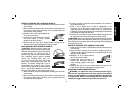
1. Remove guard and flanges from tool.
2. Remove the four corner screws attaching the gear case to
motor housing.
3. Separating the gear case from motor housing not more than
1/4" (6.35 mm), rotate the gear case head to desired position.
NOTE: If the gear case and motor housing become separated
by more than 1/4" (6.35 mm), the tool must be serviced and
re-assembled by a D
EWALT service center. Failure to have the
tool serviced may cause brush, motor and bearing failure.
4. Re-install screws to attach the gear case to the motor housing.
Tighten screws to 18 in./lbs. (2.03 Nm) torque. Overtightening
could cause screws to strip.
5. Re-install guard and correct flanges for the appropriate
accessories.
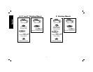
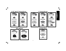
Accessories
It is important to choose the correct guards, backing pads and
flanges to use with grinder accessories. See pages 7–9 for
information on choosing the correct accessories.