


20 en - 5
ENGLISH
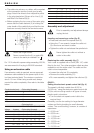
Adjusting the depth of cut (fig. D)
Your router is equipped with a high precision depth
adjustment system including a zero reset ring for
both the quick adjuster and the fine adjuster.
Quick adjustment using the graduation with zero
reset ring
• Loosen the depth stop locking bolt (14).
• Unlock the plunge limiter (15) by turning it
counterclockwise.
• Lower the router carriage until the cutter is in
contact with the workpiece.
• Tighten the plunge limiter (15).
• Set the quick adjuster (16) to zero using the ring
(22). The depth stop (13) must be in contact with
the revolver depth stop (12).
• Adjust the depth of cut using the quick adjuster (16)
and the corresponding graduation. The adjusted
depth of cut is indicated by the arrows (23).
• Tighten the depth stop locking bolt (14).
Triple depth adjustment using the revolver
depth stop
The revolver depth stop (12) can be used to set
3 different depths. This is particularly useful for deep
cuts, performed in steps.
• Place a depth template between the depth stop
(13) and the revolver depth stop (12) to adjust the
exact cutting depth.
• If required, set all three screws.
Fine adjustment
When not using a depth template, or if the depth of
cut needs readjustment, it is recommended to use
the fine adjuster (17).
• Adjust the depth of cut as described above.
• Set the fine adjuster to zero using the ring (24).
• Rotate the fine adjuster (17) to the required
position: one turn corresponds to approximately
1 mm and 1 mark to 0.1 mm.
Depth adjustment with router installed in inverted
position (fig. D)
• Remove the depth stop (13) and replace it with
the depth stop (DE6956) available as an option.
• Connect the threaded rod of the depth stop
(13A) to the revolver depth stop (12).
• Set the depth of cut using the adjuster on the
depth stop (13A).
For installing the router in inverted
position, refer to the relevant instruction
manual on the stationary tool.
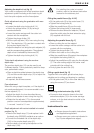
Fitting the parallel fence (fig. A & E)
• Fit the guide rods (5) to the router base (10).
• Tighten the locking bolts (9).
• Slide the parallel fence (8) over the rods.
• Tighten the locking bolts (4) temporarily.
• Remove the dust extraction adaptor (18) and
close the outlet using the dust extraction plug
(25) supplied with the tool.
Adjusting the parallel fence (fig. F)
• Draw a cutting line on the material.
• Lower the router carriage until the cutter is in
contact with the workpiece.
• Tighten the plunge limiter (15).
• Position the router on the cutting line.
• Slide the parallel fence (8) against the workpiece
and tighten the locking bolts (4).
• Adjust the parallel fence (8) using the fine adjuster
(7). The outer cutting edge of the cutter must
coincide with the cutting line.
• Firmly tighten the end lock (20).
Fitting a guide bush (fig. G)
Together with a template, guide bushes play a
valuable part in cutting and shaping to a pattern.
• Fit the guide bush (26) to the router base (10)
using the screws (27) as shown.
Connecting a dust extractor (fig. A & E)
• Connect a dust extractor hose to the dust
extraction adaptor (18) in the router carriage
column, or to the dust extraction outlet in the
parallel fence (6).
Instructions for use
• Always observe the safety instructions
and applicable regulations.
• Always move your router as indicated in
fig. H (outer edges/inner edges).