


4
Specifications
Table Size: 19 1/4” (489 mm) x 26 1/2” (673 mm)
Mitre Angle: 30º L&R
Bevel Angle: 0° to 45°L
Blade Size: 10” (254 mm)
Max. Cut Depth: 0° Bevel ..........3 1/8” (79 mm)
Max. Cut Depth: 45° Bevel ..........2 1/4” (57 mm)
RPM, no load: 3650 rpm
Unpacking
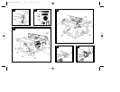
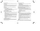
Open the box and slide the saw out, as shown in Fig. 1.
Carefully unpack the table saw and all loose items from the carton. Examine all parts
to make sure that parts have not been damaged during shipping. If any parts are
missing or damaged, contact your dealer to replace them before attempting to
assemble the tool.
Examine Fig. 3 & 4 to become familiar with the saw and its various parts. The
following sections on assembly and adjustments will refer to these terms and you must
know what and where the parts are.
ASSEMBLY
YOUR SAW SHOULD BE ASSEMBLED IN THE FOLLOWING ORDER:
1. Blade
2. Rip fence (NOTE: Adjust rip scale before proceeding. See “Adjusting Rip Scale”
pg 5).
3. Blade guard
4. Throat plate
Tools needed for assembly include a screwdriver and the wrenches included with
your saw.
ASSEMBLING THE RIP FENCE
The rip fence can be installed on the left or right side of your table saw.
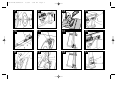
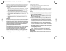
1. Locate the pin and opening on fence rails, as shown in Figure 5. Align the pin
with the slot and align the latch with the opening.
2. Secure the rip fence by snapping the latches onto the rails as shown in
Figure 6. Be sure to snap both latches in place.
ATTACHING/REPLACING THE BLADE
1. THE SAW MUST BE UNPLUGGED BEFORE YOU MAKE ANY
ADJUSTMENT TO THE BLADE.
2. Raise the saw blade arbor to its maximum height by turning the blade height
adjustment wheel clockwise.
3. Remove the arbor nut and flange from the saw arbor by turning
counterclockwise.
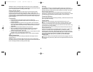
4. Place the saw blade on to the spindle making sure the teeth of the blade point
down at the front of the table. Assemble the washers and arbor nut to the spindle
and tighten arbor nut as far as possible by hand, making sure that the saw blade
is against the inner washer and the large washer diameters are against the
blade. Ensure the side of outer washer marked “Blade Side” is against the blade
(see Fig. 7). Ensure the spindle and washers are free from dust and debris.
5. To keep the spindle from rotating when tightening the arbor nut, use the open-
ended spindle wrench to secure the spindle (see Fig 8).
6. Using the arbor wrench, tighten arbor nut by turning it clockwise (see Fig. 8).
7. NOTE: Different types of blades make different kerfs (width of cuts). Therefore, it
is necessary to check adjustment of rip fence pointer and blade guard splitter
when changing blades.
ADJUST BLADE ALIGNMENT TO TABLE
1. THE SAW MUST BE UNPLUGGED BEFORE YOU MAKE ANY
ADJUSTMENT TO THE BLADE.
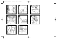
2. Place the unit in an upright position. Using a 10 mm socket, loosen rear pivot
bracket fasteners just enough to allow the bracket to move side-to-side. (Fig. 7a)
3. Adjust the bracket until the blade is parallel to the mitre gauge slot.
4. Tighten the rear pivot bracket fasteners to 7-8 lb-ft (9-11 Nm).
ADJUSTING THE RIP SCALE
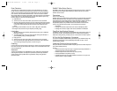
1. Unlock the rail lock lever (see Fig. 9).
2. Set the blade at 0° bevel and move the fence in until it touches the blade.
3. Lock the rail lock lever.
4. Loosen the rip scale pointer screws (see Fig. 16) and set the rip scale pointer to
read zero (0). Retighten the rip scale pointer screws. The rip scale reads
correctly only when the fence is mounted on the right side of the blade.
ATTACHING THE BLADE GUARD
1. Raise the saw blade arbor to its maximum height by turning the blade height
adjustment wheel clockwise.
2. Loosen, but do not remove the two bolts shown in Fig. 10.
3. Align the slots on the blade guard with the bolts shown in Fig. 10. Insert the
DW744-XE/387486-01 5/1/02 3:44 PM Page 12