


15
English
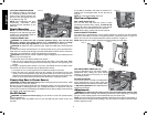
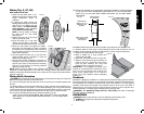
WARNING: Use featherboards for all non-thru-sawing operations where the blade guard
assembly, anti-kickback assembly and riving knife cannot be used. Always replace the
blade guard assembly, anti-kickback assembly and riving knife when the non-thru-
sawing operation is complete. Make sure the featherboard presses only on the portion
of the workpiece in front of the blade.
FIG. 42
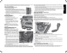
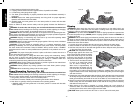
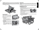
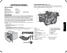
Dust Collection
Your table saw is equipped with a dust shroud
FIG. 43
VV
UU
and dust collection port. For best results,
connect a vacuum to the port at the rear of the
saw.
After extended use, the saw’s dust collection
system may become clogged. To clear the
dust collection system:
1. Unplug the saw.
2. Turn the saw on its side, so the bottom,
open part of the unit is accessible.
3. Open the dust access door (UU) shown
in Figure 43 by removing the wing screws
(VV). Clean out the excess dust, and re-secure the access door with the wing screws.
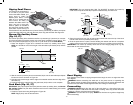
Lubrication
FIG. 44
1. All motor bearings are permanently lubricated
at the factory and no additional lubrication is
needed.
2. The height adjustment gear may require
periodic cleaning and lubrication (Fig. 44). If
you have difficulty raising or lowering
the blade, contact a D
EWALT authorized
service center.
Accessories
WARNING: Since accessories, other than those offered by DEWALT, have not been
tested with this product, use of such accessories with this tool could be hazardous. To
reduce the risk of injury, only D
EWALT recommended accessories should be used with
this product.
If you need assistance in locating any accessory, please contact D
EWALT Industrial Tool
Co., 701 East Joppa Road, Baltimore, MD 21286, call 1-800-4-D
EWALT (1-800-433-9258)
or visit our website www.D
EWALT.com.
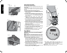
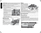
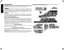
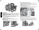
STORAGE (Fig. 45, 46)
1. Attach push stick (U) to fence.
2. Remove Blade guard assembly. See To Remove Blade guard assembly. Slide Blade
guard assembly into brackets as shown.
3. Depress the stem (GG) on the anti- kickback
A4
FIG. 45
Q
GG
assembly (Q) to allow the assembly to slide from the
riving knife slot.
4. Position anti-kickback assembly into the storage hole
as shown. While depressing stem (GG) slide the anti-
kickback assembly across the storage slot (A4) and
release pin to lock into place.
5. Loosen the riving knife lock knob (YY, Fig. 25)
(minimum of three turns).
6. Push riving knife lock knob (YY) toward the riving knife as indicated by the yellow arrows
on the knob to disengage riving knife lock pin.
7. Lift and slide the riving knife from saw.
8. Remove wingnut securing blade wrenches. Place riving knife onto post with blade
wrenches and secure with wingnut.
FIG. 46
U
D
FF
Q
V