


7
English
YY
FIG. 8A
FIG. 8B
FF
C
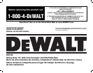
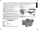
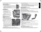
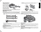
4. Lift and slide the riving knife to the approximate position indicated by the markings (non-
thru and thru-position) on the riving knife and the lock pin will snap into place.
5. Tighten the riving knife lock knob.
WARNING: Before connecting the table saw to the power source or operating the
saw, always inspect the blade guard assembly and riving knife for proper alignment and
clearance with saw blade. Check alignment after each change of bevel angle.
NOTE: DO NOT operate saw if riving knife is not locked in the thru-cut (ZZ) or non thru-cut
position (A1) hole.
When properly aligned, the riving knife will be in line with the blade at both table top level, and
at the top of the blade. Using a straight edge, ensure that the blade (B) is aligned with the
riving knife (FF) as shown in Figure 8B. With power disconnected, operate the blade tilt and
height adjustments through the extremes of travel and insure the blade guard assembly clears
the blade in all operations and that the anti-kickback assembly is functioning.
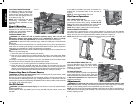
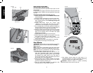
TO REPLACE THE THROAT PLATE
1. Align the throat plate as shown in Figure 7A, and insert the tabs on the back of the throat
plate into the holes on the back of the table opening.
2. Rotate cam counterclockwise until the front of throat plate drops into place. Secure
by rotating cam lock knob (CC) clockwise 1/4 turn (when cam lock is under the table
holding the throat plate in place).
3. The throat plate includes four adjustment screws which raise or lower the throat plate.
When properly adjusted, the front of the throat plate should be flush or slightly below
the surface of the table top and secured in place. The rear of the throat plate should be
flush or slightly above the table top.
WARNING: To reduce the risk of serious personal injury, the throat plate must be locked
in place at all times.
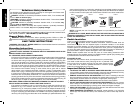
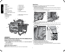
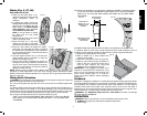
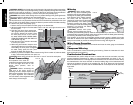
Anti-Kickback Assembly (Fig. 9)
WARNING: To reduce the risk of serious personal injury, the anti-kickback assembly
must be in place for all possible cuts.
1. Remove the anti-kickback assembly (Q) from the storage position. See Storage
(page 14).
2. Locate the anti-kickback mounting hole and slot (EE) at the top of the riving knife (FF).
3. Slide the anti-kickback housing along the top of the riving knife until the stem (GG) locates
the slot above the mounting hole. Depress the stem (GG) on the anti-kickback assembly to
allow the assembly to drop into the hole (EE). Push down on the anti-kickback assembly
until it snaps into place and locks the assembly. NOTE: Pull up on the anti-kickback
assembly to ensure it has locked into place.
GG
Q
FF
FIG. 9
EE
Q
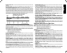
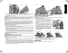
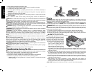
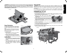
Blade guard assembly (Fig. 10, 11)
TO ATTACH BLADE GUARD ASSEMBLY
WARNING: To reduce the risk of serious personal injury, the blade guard assembly must
be in place for all possible cuts.
1. While holding the blade guard assembly (D) in a
HH
D
FIG. 10
II
vertical position slide the locating pin (HH) into the
riving knife slot (II) centering the riving knife within
the v-shaped notch in the top guard. See
Figure 10.
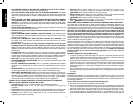
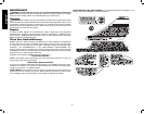
2. Rotate the blade guard assembly towards the front
of the saw while keeping the pin (HH) at the top of
the riving knife slot. Rotate until the blade guard
assembly is parallel to the table. See Figure 11.
3. Press the blade guard lock lever (WW) down until it
snaps into the locked position. Check to make sure
the guard is locked onto the riving knife. If the guard
is not locked the blade guard lock lever will flip up to
the unlocked position.
WW
FIG. 11 FIG. 11A FIG. 11B
WW
TO REMOVE THE BLADE GUARD ASSEMBLY
1. Lift the blade guard assembly lock lever (WW) to the unlocked position.
2. Rotate the guard back and slide pin from riving knife slot.
Miter Gauge
NOTE: A large auxiliary miter gauge face may be used.