


English
4
ice center for recycling. If the new battery pack elicits the same trouble indication as the
original, have charger tested at an authorized service center.
OPERATION
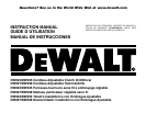
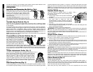
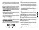
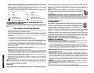
Installing and Removing the Battery Pack
NOTE: Make sure your battery pack is fully charged.
To install the battery pack into the tool handle, align
the base of the tool with the notch inside the tool’s
handle (FIG. 1) and slide the battery pack firmly into
the handle until you hear the lock snap into place as
shown in FIG. 1A.
To remove the battery pack
from the tool, press the
release buttons and firmly pull the battery pack out of
the tool handle. Insert it into the charger as described in the charger section of this manu-
al.
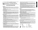
Variable Speed Switch (Fig. 2)
To turn the tool on, squeeze the trigger switch. To turn the tool off, release the trigger
switch. Your tool is equipped with a brake. The chuck will stop as soon as the trigger switch
is fully released.
The variable speed switch enables you to select the best speed for a particular application.
The farther you squeeze the trigger, the faster the tool will operate. Use lower speeds for
starting holes without a centerpunch, drilling in metals or plastics, driving screws and
drilling ceramics, or in any application requiring high torque. Higher speeds are better for
drilling in wood, wood compositions and for using abrasive and polishing accessories. For
maximum tool life, use variable speed only for starting holes or fasteners.
NOTE: Continuous use in variable speed range is not recommended. It may damage the
switch and should be avoided.
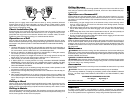
Forward/Reverse Control Button (Fig. 2)
A forward/reverse control button deter
mines the direction the tool will spin and
also serves as a lock off button. To
select forward rotation, release the trig-
ger switch and depress the forward/re-
verse control button on the right side of
the tool.To select reverse, depress the
forward/reverse control button on the left side of the tool. The center position of the control
button locks the tool in the off position. When changing the position of the control button,
be sure the trigger is released. NOTE: The first time the tool is run after changing the direc-
tion of rotation, you may hear a click on start up. This is normal and does not indicate a
problem.
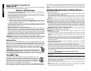
Torque Adjustment Collar (Fig. 3)
Your tool has an adjustable torque screwdriver mechanism for
driving and removing a wide array of fastener shapes and sizes
and a hammer mechanism for drilling into masonry. Circling the
collar are numbers, a drill bit symbol, and a hammer symbol.
These numbers are used to set the clutch to deliver a torque
range. The higher the number on the collar, the higher the torque
and the larger the fastener which can be driven. To select any of
the numbers, rotate until the desired number aligns with the
arrow.
Dual Range Gearing (Fig. 3)
The dual range feature of your tool allows you to shift gears for greater versatility. To select
the low speed, high torque setting, turn the tool off and permit to stop. Slide the gear shifter
FIG. 3
FIG. 2
FIG. 1A
forward (towards the chuck) (position 1), as shown. To select the high speed, low torque
setting, turn the tool off and permit to stop. Slide the gear shifter back (away from chuck).
NOTE Do not change gears when the tool is running. If you are having trouble changing
gears, make sure that the dual range gear shifter is either completely pushed forward or
completely pushed back.
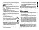
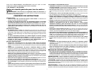
Keyless Chuck (Fig. 4)
Your tool features a keyless chuck for greater
convenience. To insert a drill bit or other accessory, follow
the steps listed below.
1. Lock the trigger switch in the off position as described
on page 6.
2. Grasp the rear half of the chuck with one hand and use
your other hand to rotate the front half
counterclockwise, as shown. Rotate far enough so
that the chuck opens sufficiently to accept the desired
accessory.
3. Insert the bit or other accessory about 3/4” into the
chuck and tighten securely by holding the rear half of the chuck and rotating the front
portion in the clockwise direction.
To release the accessory, repeat step 2 listed above.
WARNING: Do not attempt to tighten drill bits (or any other accessory) by gripping the
front part of the chuck and turning the tool on. Damage to the chuck and personal injury
may result. Always lock off trigger switch when changing accessories.
Be sure to tighten chuck with two hands on both the rear sleeve and the forward sleeve for
maximum tightness.
Single Sleeve Chuck
Some tools feature a keyless chuck with one plastic sleeve for one-handed operation of
the chuck. To insert a drill bit or other accessory, follow the steps below.
1. Lock the trigger in the off position as described on page 6.
2. Grasp the black sleeve of the chuck with one hand and use the other hand to secure
the tool as shown. Rotate the sleeve counterclockwise far enough so that the chuck
opens sufficiently to accept the desired accessory.
3. Insert the accessory about 3/4” into the chuck and tighten securely by rotating the chuck
sleeve clockwise with one hand while holding the tool with the other.
To release the accessory, repeat step 2 listed above.
WARNING: Do not attempt to tighten drill bits (or any other accessory) by gripping the
front part of the chuck and turning the tool on. Damage to the chuck and personal injury
may result. Always lock off trigger switch when changing accessories.
Be sure to tighten chuck with one hand on the chuck sleeve and one hand holding the tool
for maximum tightness.
NOTE: Do not install a single-sleeve chuck onto a tool that has a standare two-sleeve, key-
less chuck. Tools originally built with a single sleeve chuck have an internal locking mech-
anism that is not part of the chuck. Therefore, the single-sleeve chuck will not function
properly on tools originally built with standard two-sleeve chucks.
Chuck Removal (Fig. 5)
Always wear eye protection.
Turn the adjustment collar to the “drill” position and low speed gear shifter position 1.
Tighten the chuck around the shorter end of a hex key (not supplied) of 1/4” or greater size.
Using a wooden mallet or similar object, strike the longer end in the clockwise direction, as
shown. This will loosen the screw inside the chuck.
Open chuck jaws fully, insert screwdriver (or Torx tool if required) into front of chuck
FIG. 4