


45º bevel - Left
Max. Height 2.4" (61 mm) Result Width 12.9" (328 mm)
Max. Width 13.6" (345 mm) Result Height 1.9" (48 mm)
45º bevel - Right
Max. Height 1.7' (43 mm) Result Width 12.9" (328 mm)
Max. Width 13.6" (345 mm) Result Height 1.1" (28 mm)
Your saw is capable of cutting baseboard moldings 0.8" (20 mm) thick by 6.5" (165 mm) tall
on a 45º right or left miter.
NOTE: Your saw is capable of cutting the following once a special setup procedure is followed
Refer to Special Cuts.
0º miter height 1.5 (38 mm) width 16.1 (409 mm)
45º miter height 1.5 (38 mm) width 11.7 (297 mm)
DRIVE
120 Volt Motor
1600 Watts In 15 Amp Motor
3600 RPM Cut Helical Gears
Multi-V Belt Roller Bearings
Automatic Electric Brake Carbide Blade
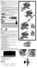
Familiarization
Your miter saw is fully assembled in the car ton. Open the box and lift the saw out by the
con venient carry ing handle, as shown in Figure 2.
Place the saw on a smooth, flat surface such as a workbench or strong table.
Examine Figure 4 to become familiar with the saw and its various parts. The section on adjus-
tments will refer to these terms and you must know what and where the parts are.
CAUTION: Pinch Hazard. To reduce the risk of injury, keep thumb underneath the handle
when pulling the handle down. The lower guard will move up as the handle is pulled down
which could cause pinching. The handle is placed close to the guard for special cuts.
Press down lightly on the operating handle and pull out the lock down pin. Gently release the
downward pressure and hold the arm allowing it to rise to its full height. Use the lock down pin
when carrying the saw from one place to another. Always use the carrying handle to transport
the saw or the hand indentations shown in Figure 4.
Bench Mounting
Holes are provided in all 4 feet to facilitate bench mounting, as shown in Figure 4. (Two dif-
ferent sized holes are provided to accommodate different sizes of screws. Use either hole, it
is not necessary to use both.) Always mount your saw firmly to a stable surface to prevent
movement. To enhance the tool’s portability, it can be mounted to a piece of 1/2" (12.7 mm) or
thicker plywood which can then be clamped to your work support or moved to other job sites
and reclamped.
NOTE: If you elect to mount your saw to a piece of plywood, make sure that the mounting
screws don’t protrude from the bottom of the wood. The plywood must sit flush on the work
support. When clamping the saw to any work surface, clamp only on the clamping bosses
where the mounting screw holes are located. Clamping at any other point will surely interfere
with the proper operation of the saw.
CAUTION: To prevent binding and inaccuracy, be sure the mounting surface is not warped or
otherwise uneven. If the saw rocks on the surface place a thin piece of material under one saw
foot until the saw sits firmly on the mounting surface.
IMPORTANT SAFETY INSTRUCTIONS
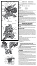
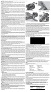
Changing or Installing a New Saw Blade (Fig. 3)
WARNING: To reduce the risk of serious personal injury, turn off the tool and disconnect
it from the power source before attempting to move it, change accessories or make any
adjustments accept as written in laser adjustment instructions.
CAUTION:
• Never depress the spindle lock button while the blade is under power or coasting.
• Do not cut ferrous metal (containing iron or steel) or masonry or fiber cement product
with this miter saw.
Removing the Blade
1. Unplug the saw.
2. Raise the arm to the upper position and raise the lower guard (A) as far as possible.
3. Loosen, but do not remove guard bracket screw (B) until the bracket can be raised far
enough to access the blade screw. Lower guard will remain raised due to the position of
the guard bracket screw.
4. Depress the spindle lock button (C) while carefully rotating the saw blade by hand until the
lock engages.
5. Keeping the button depressed, use the other hand and the wrench provided (D) to loosen
the blade screw. (Turn clockwise, left-hand threads.)
6. Remove the blade screw (E), outer clamp washer (F), blade (G) and blade adapter (H), if
used. The inner clamp washer (I), may be left on the spindle.
NOTE: For blades with a blade hole of 5/8" (15.88 mm), the 1" (25.4 mm) blade adapter (H)
is not used.
Installing a Blade
1. Unplug the saw.
2. With the arm raised, the lower guard held open and the guard bracket raised, place the
blade on the spindle, onto the blade adapter [if using a blade with a 1” (25.4mm) diameter
blade hole] and against the inner blade clamp with the teeth at the bottom of the blade
pointing toward the back of the saw.
3. Assemble the outer blade clamp onto the spindle.
4. Install the blade screw and, engaging the spindle lock, tighten the screw firmly with wrench
provided. (Turn counterclockwise, left-hand threads.)
NOTE: When using blades with a 5/8" (15.88 mm) diameter blade hole, the blade adapter will
not be used and should be stored in a safe place for future use.
5. Return the guard bracket to its original position and firmly tighten the guard bracket screw
to hold bracket in place.
WARNING:
• The guard bracket must be returned to its original position
and the screw tightened before activating the saw.
• Failure to do so may allow the guard to contact the spinning
saw blade resulting in damage to the saw and severe personal
injury.
Transporting the Saw
WARNING: To reduce the risk of serious personal injury, turn off the tool and disconnect
it from the power source before attempting to move it, change accessories or make any
adjustments accept as written in laser adjustment instructions.
WARNING: To reduce the risk of serious personal injury, ALWAYS lock the rail lock
knob, miter lock handle, bevel lock handle, lock down pin and fence adjustment knobs before
transporting saw.
In order to conveniently carry the miter saw from place to place, a carrying handle has been
included on the top of the saw arm and hand indentations in the base, as shown in Figure 4.
ADJUSTMENTS
WARNING: To reduce the risk of serious personal injury, turn off the tool and disconnect
it from the power source before attempting to move it, change accessories or make any
adjustments accept as written in laser adjustment instructions.
NOTE: Your miter saw is fully and accurately adjusted at the factory at the time of manufacture.
If readjustment due to shipping and handling or any other reason is required, follow the steps
below to adjust your saw.
Once made, these adjustments should remain accurate. Take a little time now to follow these
directions carefully to maintain the accuracy of which your saw is capable.
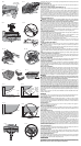
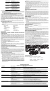
MITER SCALE ADJUSTMENT (FIG. 5)
Place a square against the saw’s fence and blade, as shown. (Do not touch the tips of the blade
teeth with the square. To do so will cause an inaccurate measure ment.) Loosen the miter lock
handle and swing the miter arm until the miter latch locks it at the 0 miter position. Do not
tighten the lock handle. If the saw blade is not exactly perpendicular to the fence, loosen the
four screws that hold the miter scale to the base and move the scale left or right until the blade
is perpendicular to the fence, as measured with the square. Retighten the four screws. Pay no
attention to the reading of the miter pointer at this time.
MITER POINTER ADJUSTMENT (FIG. 6, 7)
Loosen the miter lock handle to move the miter arm to the zero position. With the miter lock
handle loose allow the miter latch to snap into place as you rotate the miter arm to zero.
Observe the pointer and miter scale shown in Figure 6. If the pointer does not indicate exactly
zero, loosen the screw holding the pointer in place, reposition the pointer and tighten the
screw.
BEVEL SQUARE TO TABLE ADJUSTMENT (FIG. 8)
To align the blade square to the table, lock the arm in the down position. Place a square against
the blade and table taking care to have the square not touch a blade tooth. Loosen the bevel
lock handle and ensure the bevel latch has firmly snapped into place at 0º. If the saw blade is
not exactly perpendicular to the table, loosen the three nuts which hold the bevel detent plates
to the table. Adjust the center nut to allow slight drag between it and the table. Gently tap
the motor or the belt cover to move the upper assembly until the blade is square to the table.
FIG. 5
MITER
SCALE
FIG. 6
MITER
POINTER
KERF
PLATE
FIG. 4
MOTOR
HOUSING
RAIL SET
SCREW
ADJUSTMENT
RAIL LOCK
KNOB
MOTOR
ENDCAP
BEVEL LATCH
LEVER
[one each side]
BEVEL LOCK
HANDLE
BEVEL SCALE
(one each side)
LOCK DOWN
PIN
MITER
LATCH
BUTTON
TABLE
MITER LATCH
OVERRIDE
MITER
SCALE
MITER LOCK
HANDLE
BLADE
WRENCH
FENCE
ADJUSTMENT
KNOB
(one each side)
BENCH MOUNTING HOLES
LIFTING
HANDLE
OPERATING HANDLE
BELT COVER
RAILS
GROOVING STOP
BEVEL LATCH
PLATES
DUST SPOUT
FENCE
HAND
INDENTATION
BLADE
GUARD
TRIGGER
SWITCH
THUMBSCREW
FIG. 8
0º BEVEL LATCH
PLATE
0º BEVEL
LOCK NUT
RIGHT 45º BEVEL
LATCH PLATE
LEFT 45º BEVEL
LATCH PLATE
RIGHT 45º
BEVEL
ADJUSTMENT
SCREW
LEFT 45º BEVEL
ADJUSTMENT
SCREW
RIGHT 45º BEVEL
PLATE LOCK NUT
LEFT 45º BEVEL
PLATE LOCK NUT
RIGHT BEVEL
POINTER
LEFT BEVEL
POINTER
FIG. 7
MITER LOCK
HANDLE
MITER LATCH
OVERRIDE
MITER
LATCH
BUTTON