


WARNING: Always use eye protection. All users and bystanders must wear eye protection
that conforms to ANSI Z87.1 (CAN/CSA Z94.3).
Plug the saw into any household 60 Hz power source. Refer to the nameplate for voltage. Be
sure the cord will not interfere with your work.
SWITCH
To turn the saw on, depress the trigger switch. To turn the tool off, release the switch. Allow
the blade to spin up to full operating rpm before making the cut. Release the trigger switch
and allow the brake to stop the blade before raising the saw head. There is no provision for
locking the switch on, but a hole is provided in the trigger for insertion of a padlock to lock the
saw off.
CUTTING WITH YOUR SAW
If the slide feature is not used, ensure the saw head is pushed back as far as possible and
the rail lock knob is tightened. This will prevent the saw from sliding along its rails as the
workpiece is engaged.
NOTE: Although this saw will cut wood and many non-ferrous materials, we will limit our
discussion to the cutting of wood only. The same guidelines apply to the other mat erials.
DO NOT CUT FERROUS (IRON AND STEEL) MAT ERIALS OR MASONRY WITH THIS SAW.
Do not use any abrasive blades.
CROSSCUTS
Cutting of multiple pieces is not recommended but can be done safely by ensuring that each
piece is held firmly against the table and fence. When the saw comes up to speed (about 1
second) lower the arm smoothly and slowly to cut through the wood. Let the blade come to a
full stop before raising arm.
A crosscut is made by cutting wood across the grain at any angle. A straight crosscut is made
with the miter arm at the zero degree position. Set and lock the miter arm at zero, hold the
wood firmly on the table and against the fence. With the rail lock knob tightened, turn on the
saw by squeezing the trigger switch shown in Figure 4.
When the saw comes up to speed (about 1 second) lower the arm smoothly and slowly to cut
through the wood. Let the blade come to a full stop before raising arm.
When cutting anything larger than a 2 x 8 (51 x 203 mm [ 2 x 6 (51 x 152) at 45º miter] use an
out-down-back motion with the rail lock knob loosened. Pull the saw out, toward you, lower
the saw head down toward the workpiece, and slowly push the saw back to complete the cut.
Do not allow the saw to contact the top of the workpiece while pulling out. The saw may run
toward you, possibly causing personal injury or damage to the workpiece.
NOTE: To provide greater crosscut capacity with reduced stroke the blade on the DW718
extends deeper into the table. As a result a greater lifting force on the workpiece may be expe-
rienced during the cut.
CAUTION: Always use a work clamp to maintain control and reduce the risk of workpiece
damage and personal injury.
NOTE: The rail lock knob shown in Figure 4 must be loose to allow the saw to slide along its
rails.
Miter crosscuts are made with the miter arm at some angle other than zero. This angle is often
45º for making corners, but can be set anywhere from zero to 50º left or right. Make the cut
as described above.
When cutting wider workpieces wider than a 2 x 6 that are shorter in length, always place the
longer side against the fence (Fig. 12).
To cut through an existing pencil line on a piece of wood, match the angle as close as possible.
Cut the wood a little too long and measure from the pencil line to the cut edge to determine
which direction to adjust the miter angle and recut. This will take some practice, but it is a
commonly used technique.
BEVEL CUTS
A bevel cut is a crosscut made with the saw blade at an angle to the wood. In order to set the
bevel, loosen the bevel lock handle, lift the bevel latch lever, Figure 4, and move the saw to the
left or right as desired. (It is necessary to move the fence to allow clearance). Once the desired
bevel angle has been set, tighten the bevel clamp handle firmly.
Bevel angles can be set from 48º right to 48º left and can be cut with the miter arm set between
50º right or 60º left. At some extreme angles, the right or left side fence might have to be
removed. To remove the left or right fence, unscrew the fence adjustment knob several turns
and slide the fence out.
QUALITY OF CUT
The smoothness of any cut depends on a number of variables. Things like material being cut,
blade type, blade sharpness and rate of cut all contribute to the quality of the cut.
When smoothest cuts are desired for molding and other precision work, a sharp (60 tooth car-
bide) blade and a slower, even cutting rate will produce the desired results.
Ensure that material does not creep while cutting, clamp it securely in place. Always let the
blade come to a full stop before raising arm.
If small fibers of wood still split out at the rear of the workpiece, stick a piece of masking tape
on the wood where the cut will be made. Saw through the tape and carefully remove tape when
finished.
For varied cutting applications, refer to the list of recommended saw blades for your saw and
select the one that best fits your needs. Refer to Saw Blades under Optional Accessories.
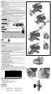
BODY AND HAND POSITION (FIG. 13A)
Proper positioning of your body and hands when operating the miter saw will make cutting
easier, more accurate and safer. Never place hands near cutting area. Place hands no closer
than 6" (152 mm) from the blade. Hold the workpiece tightly to the table and the fence
when cutting. Keep hands in position until the trigger has been released and the blade has
completely stopped. ALWAYS MAKE DRY RUNS (UNPOWERED) BEFORE FINISH CUTS SO
THAT YOU CAN CHECK THE PATH OF THE BLADE. DO NOT CROSS HANDS, AS SHOWN
IN FIGURE 13B.
Keep both feet firmly on the floor and maintain proper balance. As you move the miter arm
left and right, follow it and stand slightly to the side of the saw blade. Sight through the guard
louvers when following a pencil line.
CLAMPING THE WORKPIECE
WARNING: To reduce the risk of serious personal injury, turn off the tool and disconnect
it from the power source before attempting to move it, change accessories or make any
adjustments accept as written in laser adjustment instructions.
WARNING: A workpiece that is clamped, balanced and secure before a cut may become
unbalanced after a cut is completed. An unbalanced load may tip the saw or anything the saw
is attached to, such as a table or workbench. When making a cut that may become unbalanced,
properly support the workpiece and ensure the saw is firmly bolted to a stable surface. Personal
injury may occur.
WARNING: The clamp foot must remain clamped above the base of the saw whenever the
clamp is used. Always clamp the workpiece to the base of the saw–not to any other part of the
work area. Ensure the clamp foot is not clamped on the edge of the base of the saw.
CAUTION: Always use a work clamp to maintain control and reduce the risk of workpiece
damage and personal injury.
If you cannot secure the workpiece on the table and against the fence by hand, (irregular shape,
etc.) or your hand would be less than 6" (152 mm) from the blade, a clamp or other fixture must
be used.
For best results use the DW7082 clamp made for use with your saw. Another type of clamp
may be supplied with your DW718. To purchase the DW7082 contact your local retailer or
D
EWALT service center.
Other aids such as spring clamps, bar clamps or C-clamps may be appropriate for certain
sizes and shapes of material. Use care in selecting and placing these clamps. Take time to
make a dry run before making the cut. The left or right fence will slide from side to side to aid
in clamping.
TO INSTALL CLAMP
1. Insert it into the hole behind the fence. The clamp should be facing toward the back of the
miter saw. The groove on the clamp rod should be fully inserted into the base. Ensure this
groove is fully inserted into the base of the miter saw.
If the groove is visible, the clamp will not be secure.
2. Rotate the clamp 180º toward the front of the miter saw.
3. Loosen the knob to adjust the clamp up or down, then use the fine adjust knob to firmly
clamp the workpiece.
NOTE: Place the clamp on the opposite side of the base when beveling. ALWAYS MAKE DRY
RUNS (UNPOWERED) BEFORE FINISH CUTS TO CHECK THE PATH OF THE BLADE. ENSURE
THE CLAMP DOES NOT INTERFERE WITH THE ACTION OF THE SAW OR GUARDS.
WARNING: A workpiece that is clamped, balanced and secure before a cut may become
unbalanced after a cut is completed. An unbalanced load may tip the saw or anything the
saw is attached to, such as a table or workbench. When making a cut that may become
unbalanced, properly support the workpiece and ensure the saw is firmly bolted to a stable
surface.
WARNING: The clamp foot must remain clamped above the base of the saw whenever the
clamp is used. Always clamp the workpiece to the base of the saw–not to any other part of the
work area. Ensure the clamp foot is not clamped on the edge of the base of the saw.
SUPPORT FOR LONG PIECES
WARNING: To reduce the risk of serious personal injury, turn off the tool and disconnect
it from the power source before attempting to move it, change accessories or make any
adjustments accept as written in laser adjustment instructions.
ALWAYS SUPPORT LONG PIECES.
Never use another person as a substitute for a table extension; as additional support for a
workpiece that is longer or wider than the basic miter saw table or to help feed, support or pull
the workpiece.
For best results, use the DW7080 extension work support to extend the table width of your
saw. Available from your dealer at extra cost. Support long workpieces using any convenient
means such as sawhorses or similar devices to keep the ends from dropping.
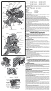
CUTTING PICTURE FRAMES, SHADOW BOXES AND OTHER FOUR-SIDED PROJECTS
To best understand how to make the items listed here, we suggest that you try a few simple
projects using scrap wood until you develop a “FEEL” for your saw.
Your saw is the perfect tool for mitering corners like the one shown in Figure 14. Sketch A in
Figure 15 shows a joint made by using the bevel adjustment to bevel the edges of the two
boards at 45º each to produce a 90º corner. For this joint the miter arm was locked in the zero
position and the bevel adjustment was locked at 45º. The wood was positioned with the broad
flat side against the table and the narrow edge against the fence. The cut could also be made
by mitering right and left with the broad surface against the fence.
CUTTING TRIM MOLDING AND OTHER FRAMES
Sketch B in Figure 15 shows a joint made by setting the miter arm at 45º to miter the two
boards to form a 90º corner. To make this type of joint, set the bevel adjustment to zero and
the miter arm to 45º. Once again, position the wood with the broad flat side on the table and
the narrow edge against the fence.
The two sketches in Figure 15 are for four side objects only.
As the number of sides changes, so do the miter and bevel angles. The chart below gives the
proper angles for a variety of shapes.
- EXAMPLES -
NO. SIDES ANGLE MITER OR BEVEL
4 45°
5 36°
6 30°
7 25.7°
8 22.5°
9 20°
10 18°
(The chart assumes that all sides are of equal length.) For a shape that is not shown in the chart,
use the following formula. 180º divided by the number of sides equals the miter (if the material
is cut vertically) or bevel angle (if the material is cut laying flat).
CUTTING COMPOUND MITERS
A compound miter is a cut made using a miter angle and a bevel angle at the same time. This
is the type of cut used to make frames or boxes with slanting sides like the one shown in
Figure 16.
NOTE: If the cutting angle varies from cut to cut, check that the bevel clamp knob and the miter
lock knob are securely tightened. These knobs must be tightened after making any changes
in bevel or miter.
The chart (Table 1) will assist you in selecting the proper bevel and miter settings for common
compound miter cuts. To use the chart, select the desired angle “A” (Fig. 16) of your project and
locate that angle on the appropriate arc in the chart. From that point follow the chart straight
down to find the correct bevel angle and straight across to find the correct miter angle.
Set your saw to the prescribed angles and make a few trial cuts. Practice fitting the cut pieces
together until you develop a feel for this procedure and feel comfortable with it.
Example: To make a 4 sided box with 26º exterior angles (Angle A, Fig. 16), use the upper
right arc. Find 26° on the arc scale. Follow the horizontal intersecting line to either side to get
miter angle setting on saw (42°). Likewise, follow the vertical intersecting line to the top or
bottom to get the bevel angle setting on the saw (18°). Always try cuts on a few scrap pieces
of wood to verify settings on saw.
CUTTING BASE MOLDING
ALWAYS MAKE A DRY RUN WITHOUT POWER BEFORE MAKING ANY CUTS.
Straight 90º cuts:
Position the wood against the fence and hold it in place as shown in Figure 11. Turn on the
saw, allow the blade to reach full speed and lower the arm smoothly through the cut.
CUTTING BASE MOLDING UP TO 6.5" (165 mm) HIGH VERTICALLY AGAINST THE
FENCE
Position material as shown in Figure 11.
All cuts made with the back of the molding against the fence and bottom of the molding against
the base.
INSIDE CORNER: OUTSIDE CORNER:
Left side Left side
1. Miter left 45° 1. Miter right at 45°
2. Save left side of cut 2. Save left side of cut
Right side Right side
1. Miter Right 45° 1. Miter left at 45°
2. Save right side of cut 2. Save right side of cut
Material up to 6.5" (159 mm) can be cut as described above.
CUTTING CROWN MOLDING
Your miter saw is better suited to the task of cutting crown molding than any tool made. In
order to fit properly, crown molding must be compound mitered with extreme accuracy.
The two flat surfaces on a given piece of crown molding are at angles that, when added
together, equal exactly 90º. Most, but not all, crown molding has a top rear angle (the section
that fits flat against the ceiling) of 52º and a bottom rear angle (the part that fits flat against the
wall) of 38º.
Your miter saw has special pre-set miter latch points at 31.62º left and right for cutting crown
molding at the proper angle and bevel stop pawls at 33.85º left and right. There is also a mark
on the Bevel scale at 33.85º.
The chart below gives the proper settings for cutting crown molding. (The numbers for the
miter and bevel settings are very precise and are not easy to accurately set on your saw.)
Since most rooms do not have angles of precisely 90º, you will have to fine tune your
settings anyway.
PRETESTING WITH SCRAP MATERIAL IS EXTREMELY IMPORTANT!
INSTRUCTIONS FOR CUTTING CROWN MOLDING LAYING FLAT AND USING THE
COMPOUND FEATURES
1. Molding laying with broad back surface down flat on saw table (Fig. 17).
2. The settings below are for All Standard (U.S.) crown molding with 52° and 38° angles.
BEVEL SETTING TYPE OF CUT
33.85° Left
LEFT SIDE, INSIDE CORNER:
1. Top of molding against fence
2. Miter table set right 31.62°
3. Save left end of cut
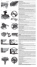
FIG. 23
SCREWS
(TWO EACH SIDE)
FIG. 24
SET SCREW
SCREWS
FIG. 26
FIG. 25
BACK FENCE