


ENGLISH
8
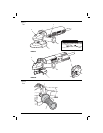
4. Tight the screw (l) holding the cinch collar
firmly around the neck of spindle (fig. 3B)
TO REMOVE THE GUARD
1. Loosen the screw (l) holding the cinch collar
around the neck of the spindle.
2. Lift up on the guard.
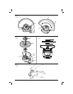
Fitting and Removing a Grinding Disc
(fi g. 1, 4, 5)
WARNING: Do not use a damaged
disc.
1. Place the tool on a table, guard up.
2. Fit the backing flange(g) correctly onto the
spindle(h) (fig. 4).
3. Place the disc(i) on the flange(g). When fitting
a disc with a raised centre, make sure that the
raised centre(j) is facing the flange(g).
4. Screw the outer flange (k) onto the spindle(h)
(fig. 5). The ring on the flange (k) must face
towards the disc when fitting a grinding disc.
5. Press the spindle lock button(b) and rotate the
spindle(h) until it locks in position.
6. Tighten the flange (k) with the two pin spanner
supplied.
7. Release the spindle lock.
8. To remove the disc, loosen the flange (k) with
the two pin spanner.
Prior to Operation
• Install the guard and appropriate disc or wheel.
Do not use excessively worn discs or wheels.
• Be sure the inner and outer flange are mounted
correctly.
• Make sure the disc or wheel rotates in the
direction of the arrows on the accessory and
the tool.
OPERATION
Instructions for Use
WARNING: Always observe the safety
instructions and applicable regulations.
WARNING: To reduce the risk
of serious personal injury, turn
tool off and disconnect tool from
power source before making any
adjustments or removing/installing
attachments or accessories. Before
reconnecting the tool, depress and
release the trigger switch to ensure that
the tool is off.
WARNING:
• Ensure all materials to be ground or
cut are secured in place.
• Apply only a gentle pressure to the
tool. Do not exert side pressure on the
disc.
• Avoid overloading. Should the tool
become hot, let it run a few minutes
under no load condition.
Proper Hand Position (fi g. 1, 6)
WARNING: To reduce the risk of
serious personal injury, ALWAYS use
proper hand position as shown.
WARNING: To reduce the risk of
serious personal injury, ALWAYS hold
securely in anticipation of a sudden
reaction.
Proper hand position requires one hand on the side
handle(d), with the other hand on the body of the
tool, as shown in Figure 6.
Switches
WARNING: Do not switch the tool on
or off when under load.
WARNING: Before using the tool,
check that the handle is tightened
securely.
SLIDER SWITCH (FIG. 1)
DWE4010
To start the tool, slide the on/off slider switch(a)
toward the front of the tool. To stop the tool, release
the on/off slider switch.
For continuous operation, slide the switch toward
the front of the tool and press the forward part of the
switch inward.
To stop the tool while operating in continuous mode,
press the rear part of the slider switch and release.
TOGGLE SWITCH (FIG. 1)
DWE4010T
To run the tool, press the switch (a) in before moving
it completely forward.
To stop the tool, move the switch (a) back the
opposite way.
To stop the tool in continuous operation, press on
the back part of the switch.