


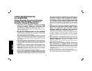
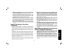
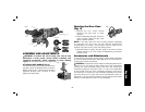
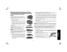
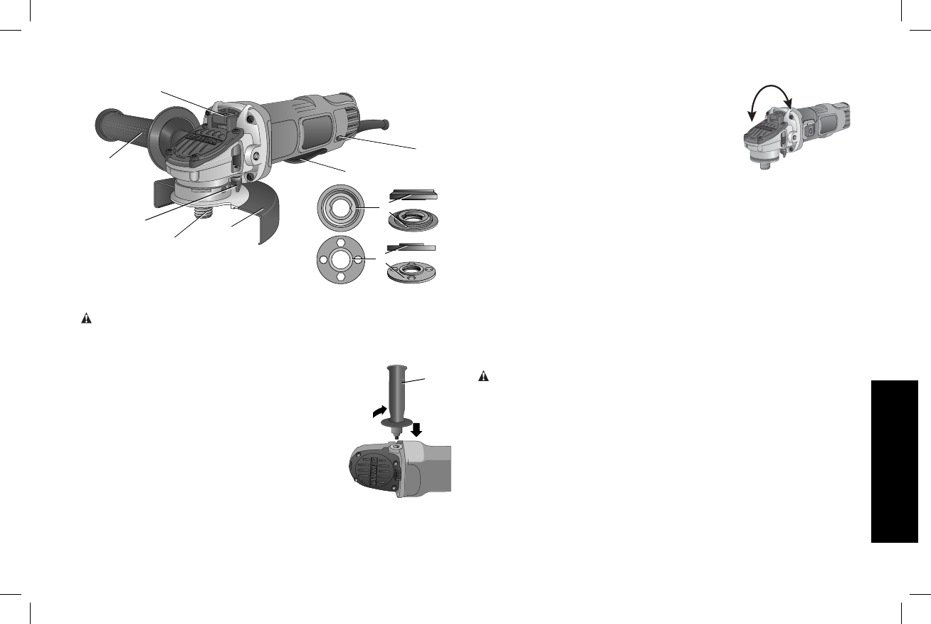
FIG. 1
E
D
H
G
A
F
C
J
B
ASSEMBLY AND ADJUSTMENTS
WARNING: To reduce the risk of injury, turn unit off and
disconnect it from power source before installing and
removing accessories, before adjusting or when making
repairs. An accidental start-up can cause injury.
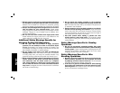
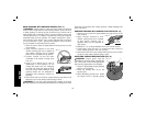
ATTACHING SIDE HANDLE (FIG. 2)
The side handle (C) can be fitted to either side of
C
FIG. 2
the gear case in the threaded holes, as shown.
Before using the tool, check that the handle is
tightened se cure ly. Use a wrench to firmly
tighten the side handle.
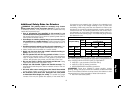
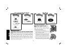
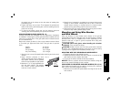
Rotating the Gear Case
(Fig. 3)
1. Remove the four corner screws
FIG. 3
90˚
90˚
attaching the gear case to motor
housing.
2. Without separating the gear case from
motor housing, rotate the gear case
head to desired position.
NOTE: If the gear case and motor housing become separated
by more than 1/8" (3.17 mm), the tool must be serviced and
re-assembled by a D
EWALT service center. Failure to have the tool
serviced may cause brush, motor and bearing failure.
3. Reinstall screws to attach the gear case to the motor housing.
Tighten screws to 18 in.-lbs. torque. Overtightening could cause
screws to strip.
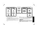
Accessories and Attachments
It is important to choose the correct guards, backing pads and flanges
to use with grinder accessories. See pages 50–51 for information on
choosing the correct accessories.
WARNING: Accessories must be rated for at least the speed recom-
mended on the tool warning label. Wheels and other accessories
running over rated accessory speed may burst and cause injury.
Threaded accessories must have a 5/8"–11 hub or M14 depending
on the spindle of the tool. Every unthreaded accessory must have a
7/8" arbor hole. If it does not, it may have been designed for a circular
saw and should not be used. Use only the accessories shown on
pages 50–51 of this manual. Accessory ratings must be above listed
minimum wheel speed as shown on tool nameplate.
English
49