


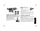
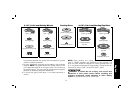
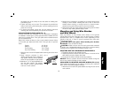


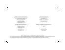
2. Apply minimum pressure to work surface,
5˚–10˚
FIG. 15
allowing the tool to operate at high
speed. Material removal rate is greatest
when the tool operates at high speed.
3. Maintain a 5˚ to 10˚ angle between
the tool and work surface for wire cup
brushes.
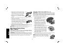
4. Maintain contact between the edge of the wheel and the work
surface with wire wheels.
5. Continuously move the tool in a forward and
FIG. 16
back motion to avoid creating gouges in the
work surface. Allowing the tool to rest on the
work surface without moving, or moving the
tool in a circular motion causes burning and
swirling marks on the work surface.
6. Remove the tool from the work surface before turning the tool off.
Allow the tool to stop rotating before setting it down.
CAUTION: Use extra care when working over an edge, as a
sudden sharp movement of grinder may be experienced.
Mounting and Using Cutting
(Type 1) Wheels
Cutting wheels include diamond wheels and abrasive discs. Abrasive
cutting wheels for metal and concrete use are available. Diamond
blades for concrete cutting can also be used.
WARNING: A closed, 2-sided cutting wheel guard is not included
with this tool but is re quired when using cutting wheels. Fail ure to
use proper flange and guard can re sult in injury resulting from wheel
breakage and wheel contact. See page 55 for more information.
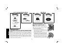
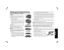
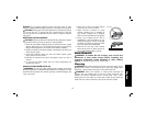
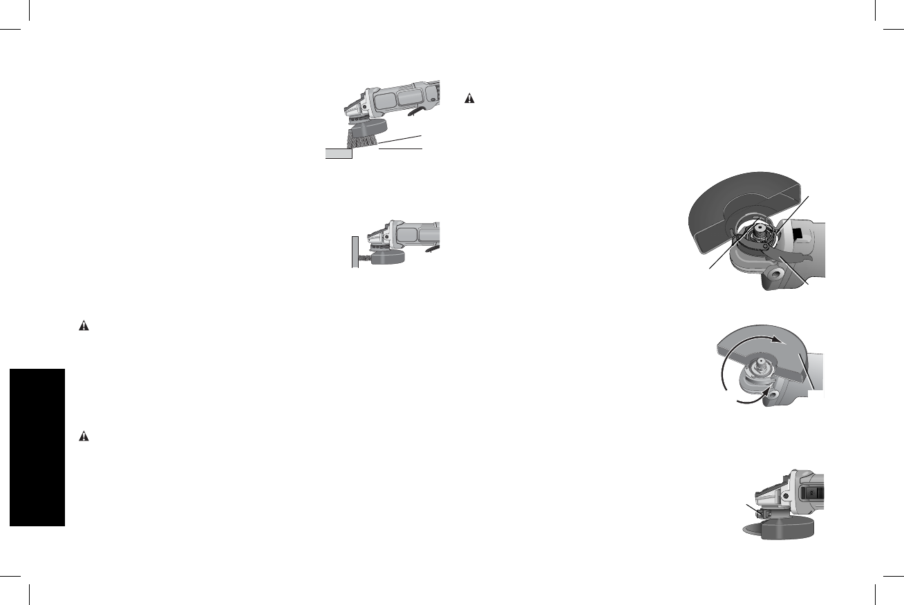
MOUNTING CLOSED (TYPE 1) GUARD (FIG. 17 – 19)
WARNING: If present, the ONE TOUCH™ guard screw, lever and
spring must be removed before attempting to mount the closed
(Type1) guard. The removed parts must be retained and reinstalled
to use the ONE TOUCH™ guard. Noting the position of these parts
before disassembly will aid in reassembly.
1. Open the guard latch (Q). Align the
Q
L
M
FIG. 17
lugs (L) on the guard with the slots
(M) on the gear case.
2. Push the guard down until the guard
lug engages and rotates freely in
the groove on the gear case hub.
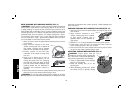
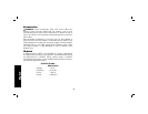
3. Rotate guard (F) into desired
working position. The guard body
should be positioned between the
spindle and the operator to provide
maximum operator protection.
4. Close the guard latch to secure the
F
FIG. 18
guard on the gear case cover. You
should be unable to rotate the guard by
hand when the latch is in closed
position. If rotation is possible, tighten
the adjusting screw (R) with clamp lever
in the closed position. Do not operate
grinder with a loose guard or clamp
lever in open position.
5. To remove the guard, open the guard latch, rotate the guard so
that the arrows are aligned and pull up on the guard.
NOTE: If, after a period of time the closed (Type 1)
R
FIG. 19
guard becomes loose, tighten the adjusting
screw (R) with the clamp lever in the closed
position.
English
56