


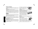

Guards and Flanges
It is important to choose the correct guards and flanges to use with
the grinder accessories. See page 50–51 and this page for the correct
accessories.
NOTE: Edge grinding and cutting can be performed with Type 27
wheels designed and specified for this purpose.
WARNING: Accessories must be rated for at least the speed recom-
mended on the tool warning label. Wheels and other accessories
running over rated accessory speed may burst and cause injury.
Every unthreaded accessory must have a 7/8" arbor hole. If it does
not, it may have been designed for a circular saw and should not be
used. Use only the accessories shown on pages 50–51. Accessory
ratings must be above listed minimum wheel speed as shown on tool
nameplate.
Switches
CAUTION: Hold the side handle and body of the tool firmly to
maintain control of the tool at start up and during use and until the
wheel or accessory stops rotating. Make sure the wheel has come to
a complete stop be fore laying the tool down.
NOTE: To reduce unexpected tool movement, do not switch the
tool on or off while under load conditions. Allow the grinder to run
up to full speed before touching the work surface. Lift the tool from
the surface before turning the tool off. Allow the tool to stop rotating
before putting it down.
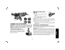
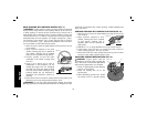
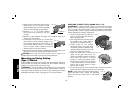
PADDLE SWITCH (DWE4120) (FIG. 6)
CAUTION: Before connecting the tool to a power source depress
and release the paddle switch (G) to ensure that the switch is off..
Depress and release the paddle switch as described above after
any interruption in power supply to the tool, such as the activation
of a ground fault interrupter, throwing of a circuit breaker, accidental
unplugging, or power failure.
To turn the tool on, push the lock-off
G
I
FIG. 6
lever (I) toward the back of the tool,
then depress the paddle switch (G).
The tool will run while the switch is
depressed. Turn the tool off by
releasing the paddle switch.
WARNING: Do not disable the lock-off lever. If the lock-off lever is
disabled, the tool may start unexpectedly when it is laid down.
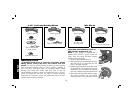
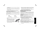
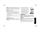
LOCK-ON BUTTON (DWE4120) (FIG. 7)
The lock-on button (H) offers increased comfort in extended use
applications. To lock the tool on, push the
H
G
I
FIG. 7
lock-off lever (I) toward the back of the
tool then depress the paddle switch (G).
With the tool running, depress the lock-
on button (H). The tool will continue to
run after the paddle switch is released. To
unlock the tool, depress and release the
paddle switch. This will cause the tool to
stop.
CAUTION: Allow the tool to reach full speed before touching tool
to the work surface. Lift the tool from the work surface before turning
the tool off.
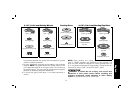
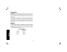
SPINDLE LOCK (FIG. 8)
The spindle lock button (A) is provided to
A
FIG. 8
prevent the spindle from rotating when
installing or removing wheels. Operate the
spindle lock only when the tool is turned off,
unplugged from the power supply, and has
come to a complete stop. Do not engage the spindle lock button
while the tool is operating because damage to the tool will result. To
engage the lock, depress the spindle lock button and rotate the
spindle until you are unable to rotate the spindle further.
English
52