


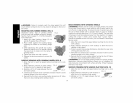
Power Source
Plug the large angle grinder into a dedicated electrical circuit.
Operating this tool on a circuit with other tools will decrease tool
performance.
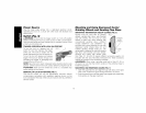
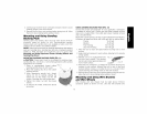
Switch (Fig. 5)
WARNING: Ensure that the trigger switch is in the off position
before connecting the tool to a power source or after a power failure.
Hold the side handle and rear handle firmly to maintain control of tool
at start up and during use.
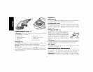
TRIGGER OPERATION WITH LOCK-ON FEATURE
To turn the tool on, depress lock off FIG.5 F
button (F) and then depress the trigger
switch (A). The lock-on button (H) will
remain depressed and tool will remain on.
To turn the tool off, depress and release
trigger. The lock pin button will pop out,
permitting the trigger to disengage and H
causing the tool to turn off.
NOTE" Allow the tool to reach full speed before touching tool to work
surface. Lift the tool from the work surface before turning the tool off.
ACAUTION: Make sure the wheel has come to a complete stop
before setting the tool down.
REMOVAL OF LOCK-ON FEATURE (FIG. 1)
The lock-on button (H) can be permanently removed without
compromising compliance with regulatory agencies shown on the
tool's nameplate. Removal of the lock pin must be done by a DEWALT
Service Center.
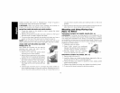
Mounting and Using Depressed Center
Grinding Wheels and Sanding Flap Discs
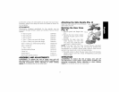
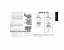
IMPORTANT INFORMATION ABOUT GUARDS (FIG. 6)
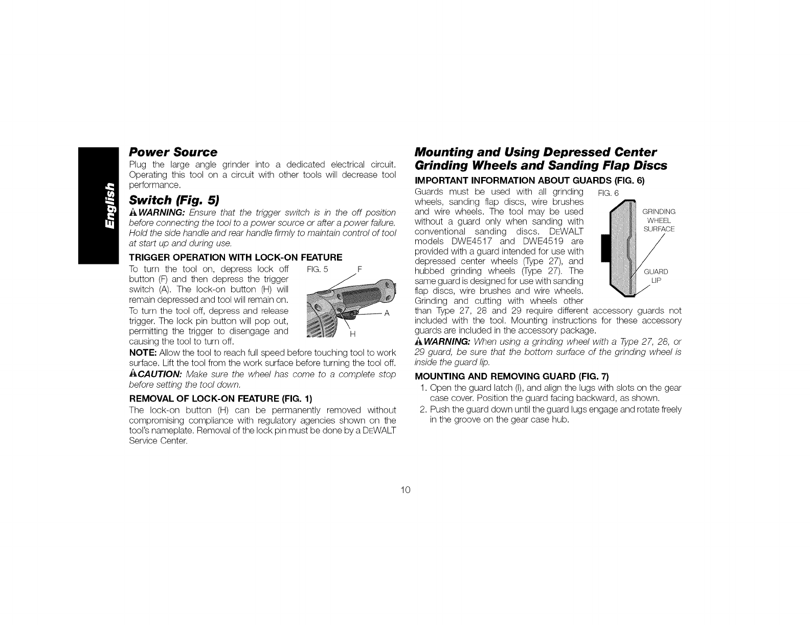
Guards must be used with all grinding FIG.6
wheels, sanding flap discs, wire brushes
and wire wheels. The tool may be used GRINDING
without a guard only when sanding with WHEEL
conventional sanding discs. DEWALT SURFACE
models DWE4517 and DWE4519 are
provided with a guard intended for use with
depressed center wheels (Type 27), and
hubbed grinding wheels (Type 27). The
same guard is designed for usewith sanding LiP
flap discs, wire brushes and wire wheels.
Grinding and cutting with wheels other
than Type 27, 28 and 29 require different accessory guards not
included with the tool. Mounting instructions for these accessory
guards are included in the accessory package.
A WARNING: When using a grinding wheel with a Type 27, 28, or
29 guard, be sure that the bottom surface of the grinding wheel is
inside the guard lip.
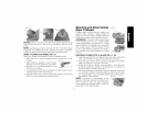
MOUNTING AND REMOVING GUARD (FIG. 7)
1. Open the guard latch (I),and align the lugs with slots on the gear
case cover. Position the guard facing backward, as shown.
2. Push the guard down until the guard lugs engage and rotate freely
in the groove on the gear case hub.
10