


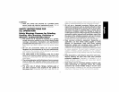
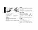

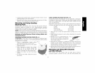
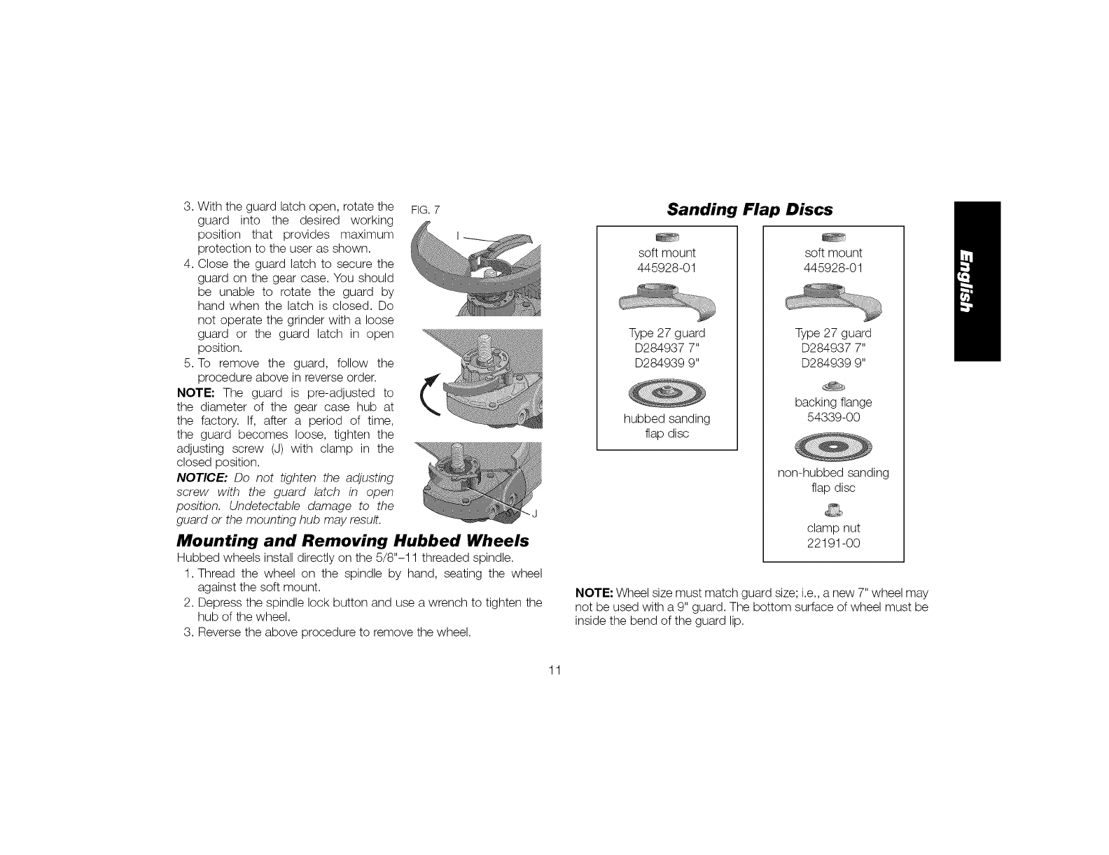
3.Withtheguardlatchopen,rotatethe FIG.7
guardintothe desiredworking
positionthat providesmaximum
protectiontotheuserasshown.
4.Closetheguardlatchtosecurethe
guardonthegearcase.Youshould
beunableto rotatetheguardby
handwhenthelatchisclosed.Do
notoperatethegrinderwithaloose
guardor theguardlatchinopen
position.
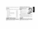
5.Toremovetheguard,followthe
procedureaboveinreverseorder.
NOTE"Theguardis pre-adjustedto
thediameterofthegearcasehubat
thefactory.If, aftera periodof time,
theguardbecomesloose,tightenthe
adjustingscrew(J)withclampin the
closedposition.
NOTICE: Do not tighten the adjusting
screw with the guard latch in open
position. Undetectable damage to the
guard or the mounting hub may result. "J
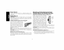
Mounting and Removing Hubbed Wheels
Hubbed wheels install directly on the 5/8"-11 threaded spindle.
1. Thread the wheel on the spindle by hand, seating the wheel
against the soft mount.
2. Depress the spindle lock button and use a wrench to tighten the
hub of the wheel.
3. Reverse the above procedure to remove the wheel.
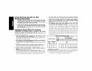
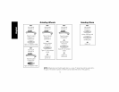
Sanding Flap Discs
soft mount
445928-01
Type 27 guard
D284937 7"
D284939 9"
hubbed sanding
flap disc
soft mount
445928-01
Type 27 guard
D284937 7"
D284939 9"
backing flange
54339-00
non-hubbed sanding
flap disc
clamp nut
22191-00
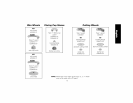
NOTE: Wheel size must match guard size; i.e., a new 7" wheel may
not be used with a 9" guard. The bottom surface of wheel must be
inside the bend of the guard lip.
11