


9
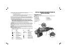
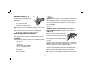
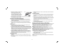
Rotating the Gear Case (Fig. 4)
For applications in which a tool will be dedicated
FIG. 4
for uses in edge grinding and finishing work, the
gear case may be rotated 90° left or right of its
original position.
1. Remove the four corner screws attaching
the gear case to motor housing.
2. Without separating the gear case from
motor housing, rotate the gear case head to
desired position.
NOTE: If the gear case and motor housing become separated by more than 3.17 mm
(1/8"), the tool must be serviced and re-assembled by a D
EWALT service center.
Failure to have the tool serviced may cause brush, motor and bearing failure.
3. Reinstall screws to attach the gear case to the motor housing. Tighten screws to
20 in.-lbs. torque. Overtightening could cause screws to strip.
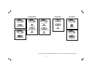
Wheel Mounting Accessories and Attachments
It is important to choose the correct guards, backing pads and flanges to use with
grinder accessories. Refer to pages 10–11 for information on choosing the correct
wheel mounting accessories.
ATTACHMENTS
Attachments designed specifically for this grinder can be purchased through DEWALT
dealers and DEWALT Factory Service centers.
9" Type 27 guard
9" Type 28 guard
7" Type 27 guard
5"–6" Type 11 flaring cup guard with flange
4" Type 11 flaring cup guard with flange
Type 11 flaring cup wheel backing flange
Type 1 flange set
7" Type 1 guard
Grinding backing flange
Clamp nut
Wheel wrench
WARNING: Accessories must be rated for at least the speed recom mended on the
tool warning label. Wheels and other accessories running over their rated accessory
speed may fly apart and cause injury. Threaded accessories must have a M14 hub.
Every unthreaded accessory must have a 22.2 mm (7/8") arbor hole. If it does not,
it may have been designed for a circular saw. Use only the accessories shown on
pages 10–11 of this manual. Accessory ratings must always be above tool speed as
shown on tool nameplate.
OPERATION
WARNING: To reduce the risk of serious personal injury, turn tool off and
disconnect tool from power source before making any adjustments or removing/
installing attachments or accessories. An accidental start-up can cause injury.
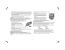
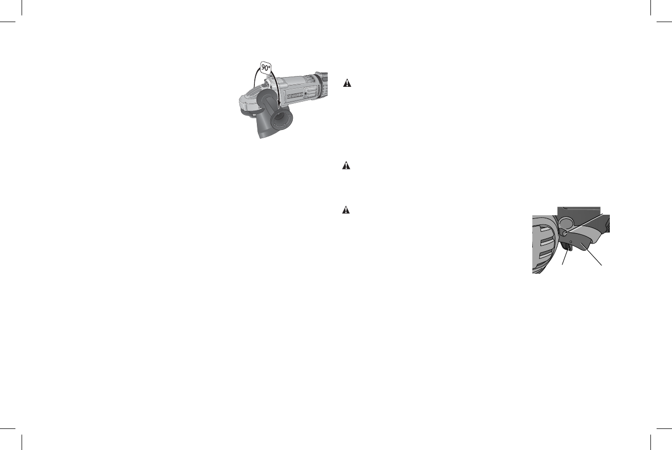
Switch (Fig. 8)
CAUTION: Before connecting the tool to a power source
A
B
C
FIG. 8
or after a power failure, depress and release the trigger
switch (A) once without depressing the lock-on button (C)
to ensure that the switch is in the off position. If the trigger
switch is locked on, the tool will start unexpectedly when
power is reconnected to the tool. Hold the side handle and
rear handle firmly to maintain control of tool at start up
and during use.
TRIGGER OPERATION
To turn the tool on, depress lock-off button (B) then trigger switch (A). The trigger can
be feathered as long as the lock-off button is depressed. The tool will remain running
while the trigger is depressed. Turn the tool off by releasing the trigger.
TRIGGER OPERATION WITH LOCK-ON FEATURE
To turn tool on, depress trigger. Depress and hold lock-on button (C) while releasing
trigger. Lock-on button will remain depressed and tool will remain on.
To turn the tool off, depress and release trigger. The lock-on button will pop out,
permitting the trigger to disengage and causing the tool to turn off.
NOTE: Allow the tool to reach full speed before touching tool to work surface. Lift the
tool from the work surface before turning the tool off.