


15
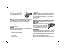
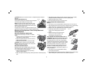
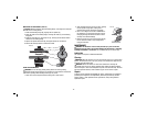
USING WIRE CUP BRUSHES AND WIRE WHEELS (FIG. 16)
Wire wheels and brushes can be used for removing rust, scale and paint, and for
smoothing irregular surfaces.
NOTE: The same precautions should be taken when wire brushing paint as when
sanding paint (refer to Precautions To Take When Sanding Paint).
1. Allow the tool to reach full speed before touching
5˚–10˚
FIG. 16
the tool to the work surface.
2. Apply minimum pressure to work surface,
allowing the tool to operate at high speed.
Material removal rate is greatest when the tool
operates at high speed.
3. Maintain a 5° to 10° angle between the tool
and work surface for wire cup brushes.
4. Maintain contact between the edge of the wheel and the work surface with wire
wheels.
5. Continuously move the tool in a forward and back motion to avoid creating
gouges in the work surface. Allowing the tool to rest on the work surface without
moving, or moving the tool in a circular motion causes burning and swirling
marks on the work surface.
6. Remove the tool from the work surface before turning the tool off. Allow the tool
to stop rotating before setting it down.
CAUTION: Use extra care when working over an edge, as a sudden sharp
movement of grinder may be experienced.
Mounting and Using Cutting Disc
Cutting wheels include diamond wheels and abrasive discs. Abrasive cutting wheels
for metal and concrete use are available. Diamond blades for concrete cutting can
also be used.
WARNING: A Type 27 cutting wheel guard is included with this tool and is required
when using cutting wheels. Fail ure to use proper flange and guard can re sult in
injury resulting from wheel breakage and wheel contact. See pages 10–11 for more
information.
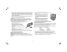
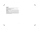
MOUNTING TYPE 27 OR TYPE 1 GUARD
1. Open the guard latch (M), and align the lugs (N)
M
N
O
FIG. 20
F
on the guard with the slots on the hub (O). This
will align the lugs with slots on the gear case
cover. Position the guard facing backward.
2. Push the guard down until the guard lug
engages and rotates freely in the groove on the
gear case hub.
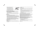
3. Rotate guard (F) into desired working position.
The guard body should be positioned between
the spindle and the operator to provide maximum
operator protection.
4. Close the guard latch to secure the guard on
the gear case cover. You should be unable to
rotate the guard by hand when the latch is in
closed position. Do not operate grinder with
a loose guard or with the guard latch in open
position.
5. To remove the guard, follow the procedure
above in reverse order.
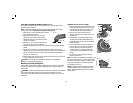
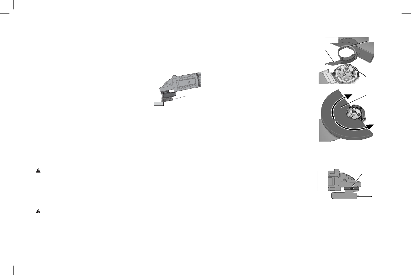
NOTE: The guard is pre-adjusted to the dia met er of the
FIG. 21
P
gear case hub at the factory. If, after a period of time,
the guard becomes loose, tighten the adjusting screw
(P) with the guard latch in the closed position with
guard installed on the tool.
NOTICE: To reduce the risk of damage to the tool, do
not tighten adjusting screw with guard latch in open
position. Undetectable damage to guard or mounting
hub may result.