


11
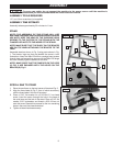
ADJUSTING BLADE TENSION
Disconnect machine from power source.
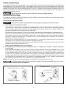
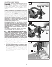
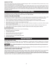
Tension is applied to the blade when the blade tension lever
(A) Fig. 7, has been adjusted and is in the vertical position
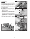
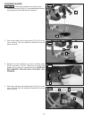
as shown. When the blade tension lever (A) is moved to
the horizontal position, as shown in Fig. 8, blade tension is
released.
To adjust blade tension, position lever (A) in the vertical
position, as shown in Fig. 7. To increase tension, turn
lever (A) clockwise and to decrease tension turn lever (A)
counterclockwise. When adjusting tension, turn lever one-
quarter of a turn at a time. NOTE: It is necessary to adjust the
blade tension only when the blade is removed from both the
upper and lower blade holders and a new or different type
of blade is used. It is not necessary to adjust blade tension
when the blade is removed and replaced in only the upper
blade holder as in performing inside cutting operations. After
desired tension is obtained, position tension lever (A) in the
horizontal position, as shown in Fig. 7.
Adjusting the blade for proper tension is usually
accomplished by trial and error. One method is to pull back
on the blade tension lever (A) Fig. 8, the blade should start to
have tension (resistance) when the blade tension lever is half
way between open Fig. 8, and closed Fig. 7 positions. Finer
blades require more tensioning while thicker blades require
less tension.
ADJUSTING CLAMPING ACTION OF UPPER
AND LOWER BLADE HOLDER CHUCK
Disconnect machine from power source.
Different widths of scroll saw blades will make it necessary
to adjust the clamping action of the upper and lower
blade holders. It should be noted, however, that very little
adjustment is necessary and very little clamping force is
required to hold the blade satisfactorily. As a rule of thumb,
looking down at the table with the table insert slot in the
6 o’clock position, resistance on the blade locking lever
should be felt when the upper blade locking lever reaches
the 7 o’clock position, or when the lower blade locking lever
reaches the 5 o’clock position.
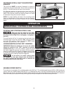
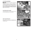
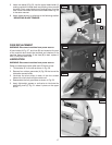
1. Move the blade locking lever (A) Fig. 9, to the rear (open)
position, as shown.
2. Turn chuck clamping knob (B) Fig. 9, clockwise to tighten
and counterclockwise to loosen the clamping action of
the blade holder chuck. Very little movement of knob (B)
will be necessary. NOTE: Only the upper chuck is shown.
Clamping action of the lower chuck is adjusted in the
same manner and can be accessed by removing dust
cup shown in Fig. 24.
11
A
Fig. 7
A
Fig. 8
A
B
Fig. 9