9
STAND
NOTE: THE ASSEMBLY OF THIS STAND WILL USE
M8X16MM CARRIAGE HEAD SCREWS AND M8 FLANGED
HEX NUTS. KEEP THE HEAD OF THE CARRIAGE HEAD
SCREWS TO THE OUTSIDE OF THE STAND WITH THE
FLANGED HEX NUTS TO THE INSIDE OF THE STAND.
NOTE: MAKE SURE THAT THE SHELF ON THE BRACES
ARE ON TOP WHEN ATTACHING THE BRACES TO THE
LEGS.
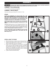
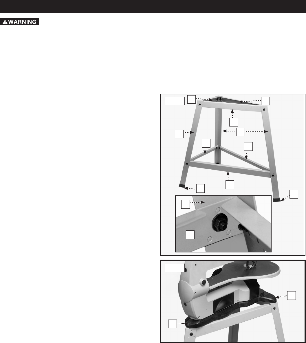
Assemble stand as shown in Fig. 2 using parts shown in Fig.
1. The braces, legs and feet are labeled the same in both
illustrations. Insert the M8x1.25x16mm carriage head screws
through legs and braces then secure with the M8x1.25 flange
hex nuts. Loosely tighten hardware at this time.
NOTE: MAKE SURE THAT THE DIMPLES ON THE LEGS
(A) FIG. 2 ARE ENGAGED WITH THE HOLES ON THE
BRACES (B). Fig. 2
SCROLL SAW TO STAND
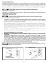
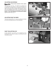
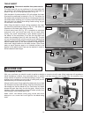
1. Place the scroll saw on the top braces of the stand Fig. 3.
2. Align the three holes (A) Fig. 3, (two of which are shown),
with the three holes in the top of the stand.
3. Place a 5/16" flat washer on a 5/16-18x1½" hex head
screw, insert the screw through the hole in the base of
the scroll saw and the hole in the stand. Place a 5/16" flat
washer, 5/16" lockwasher and thread a 5/16-18 hex nut
onto the screw. Repeat this process for the two remaining
holes in the scroll saw base and stand.
4. Tighten all stand hardware securely.
ASSEMBLY
For your own safety, do not connect the machine to the power source until the machine is
completely assembled and you read and understand the entire instruction manual.
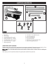
ASSEMBLY TOOLS REQUIRED
1/2" and 13mm wrenches (not supplied)
ASSEMBLY TIME ESTIMATE
Assembly takes approximately 30 minutes to 1 hour.
2
2
3
3
4
4
5
6
7
7
A
B
Fig. 2
A
A
Fig. 3


