


DL5000 INSTRUCTION MANUAL
PAGE 4 -
1) To adjust the rear roller bearings, use a small hex wrench and
loosen the set screw located on the top of the blade guide block.
Slide the blade guide block backward or forward to achieve proper
position (1/16” away from blade).
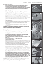
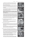
2) The blade should fit directly between the small square guides (Fig.15),
located on the front of the upper blade guide block no more than 1/16”
from the blade (Fig.16). Guides help stabilize the blade to prevent it
from twisting.
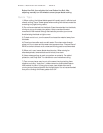
3) The blade should pass through the lower blade guide block the
same as the upper set. To adjust, loosen the set screws located on
the lower blade guide mounting block and slide blade guide arm back
or forward to adjust properly (Fig.17).
NOTE: Blade guides and blade tension should be checked and
adjusted if needed after 3 hours of use. Frequent replacement
of blade guides is recommended to maintain cutting accuracy
and extend blade life.
When pushing the material through the blade while cutting, make
sure the round support bearing behind the blade does not spin. If the
roller begins to spin, back off the pressure of feeding the material until
the spinning stops. Eventually you will begin to know the exact pressure
required to cut specific materials. NOTE: The support bearing should
not be used as a back stop for the blade to increase cutting time. This
constant contact will wear the blade down from the back side as well
as add pressure and friction to the blade until it snaps.
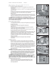
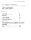
E. Upper Blade Guide Height Adjustment
The position of the upper guide should be 1/4” from the top of the
material you are cutting.
To adjust height of blade guide, loosen guide bar locking knob on
back of saw and raise or lower the guide assembly (Fig. 18).
F. Straight Edge / Angle Guide
The band saw is designed for intricate radius cuts, however the straight
edge guide will permit moderate straight edge or fixed angle cutting
when needed. Place work material against the straight edge guide and
feed the material
slowly. For easy installation, place guide in groove located on cutting
table. Adjust guide location by removing the adjusting screw and moving
guide to the various slots on the table top (Fig.19).
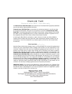
G. Blade Tracking - Upper Wheel Tracking Adjustment
The optimal position for the blade is to track in the center of all three
blade wheels but most importantly the top wheel. If the blade is not
centered, you can adjust the hub assembly screws behind the upper
wheel. This allows for the wheel to tilt, forcing a repositioning of the
blade. You will need to remove the rear cover of the machine to
expose the 6 adjusting bolts. Need photo here of hub assembly
with arrows to inner and outer bolts (Fig.20).
If the blade is coming off or riding towards the front of the top
wheel, loosen the Inner Top Hex Bolt and tighten the Outer Top
Hex Bolt, then retighten the Inner Top Hex Bolt.
If the blade is coming off or riding towards the back of the upper
wheel, loosen the Inner Bottom Hex Bolt and tighten the Outer
Set
Screw
Fig.17
Fig.16
Upper
blade
guide
Fig.15
Fig.18
Locking
Knob
Fig.19
Inner Top
Fig.20
Outer Top
Inner Bottom Outer Bottom