


2
DPLS1 Drain Panel Level Sensor/Control
Protected under one or more patents
© 2011 Mitsubishi Electric & Electronics USA, Inc.
U
L
U
L
DPLS1 Drain Pan Level Sensor/Control
Protected under one or more patients
© 2011 Mitsubishi Electric / HVAC
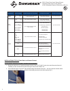
Table 1: Description of Wire Harnesses
Type of Wire
Harness
Indoor Unit Models
Connector to Indoor Unit Control
Board
Connector to Thermistor
Connector to
Control Box
M2 Wire
Harness
MS MSZ/Y
MFZ
2 pin, female connector (with black
heat shrink) to CN111
2 pin, male connector to:
RT11 (Room Temp. Thermistor)
2 pin, male connector
P Wire
Harness
PKA PCA
PEA(D)
SEZ
2 pin, female connector to CN20
2 pin, male connector to:
TH1 (Room Temp. Thermistor)
2 pin, male connector
PKFY-P**NBMU-E
PLFY-P**NCMU-E
PMFY-P**NBMU-E
PVFY-P**E00A
PEFY-P**NMHU-E
2 pin, female connector to CN20,
CN21 or CN29
2 pin, male connector to:
TH1 (Room Temp. Thermistor) or
TH22 (Pipe Temp.
Thermistor/Liquid) or
TH23 (Pipe Temp
Thermistor/Gas)
M1 Wire
Harness
PKA
PCA
PEA(D)
SEZ
PKFY-P**NH/KMU-E
PLFY-P**NBMU-E
PCFY-P**NKMU-E
PEFY-P**NMS/AU-E
4 pin, female connector to CN44
4 pin, male connector to
TH2 (Pipe Temp.
Thermistor/Liquid) and
TH5 (Pipe Temp. Thermistor/Gas)
2 pin, male connector
MS
4 pin, female connector to CN112
4 pin, male connector to
RT12 (Coil Temp. Thermistor)
MSZ/Y
4 pin, male connector to
RT12 (Coil Temp. Thermistor –
Main) and
RT13 (Coil Temp. Thermistor –
Sub)
MFZ 4 pin, female connector to CN113
4 pin, male connector to
RT15 (Coil Temp. Thermistor)
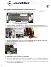
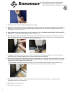
INSTALLATION OF DPLS1
Drain Pan Level Sensor/Control:
(To ensure proper performance of product, instructions must be followed.)
1. Disconnect (and lock-out, if required) all power to the Mr. Slim or CITY MULTI Indoor Unit at the Disconnect Switch (if
installed) or at the main disconnect panel serving the indoor and/or outdoor unit.
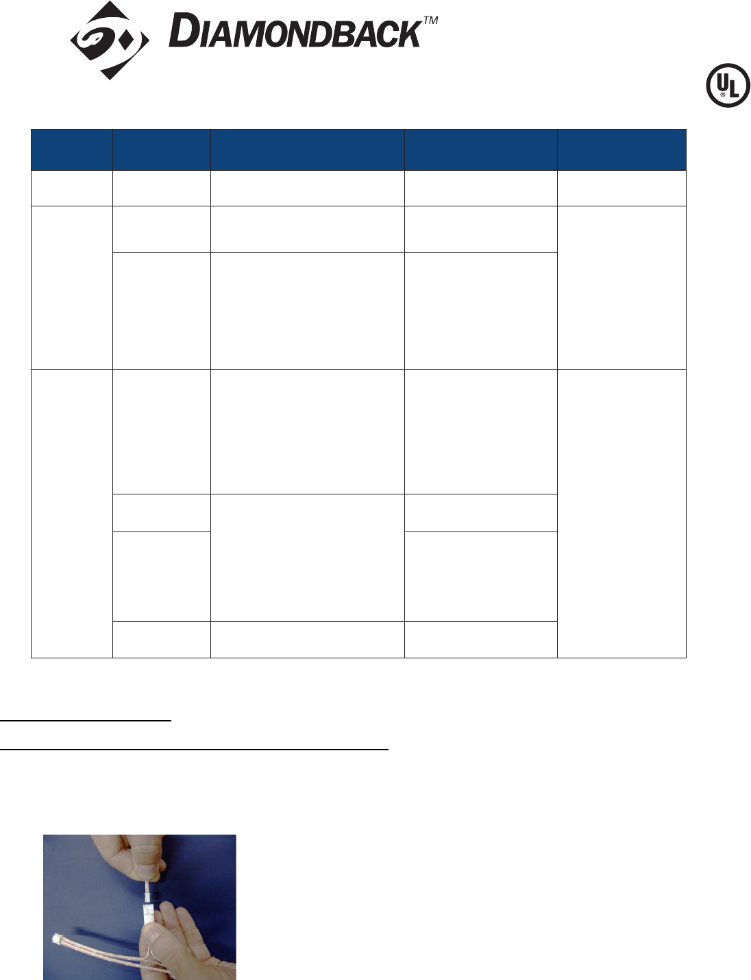
2. Connect DPLS1 Splice Connector to the selected mating Wire Harness Connector – see wiring harness selection above.
Connect the Control Box’s Splice C onnector to the mating connector on the Wire Harness (Fig 1).
Fig 1
4F Wire
Harness
All indoor units, with
CN-4F Connector on
4 pin terminate to CN-4F if available -
CN-4F is used for other function use
If CN-4F not available
2 pin, male connector
Control Board Thermistor Connection Method
Type of Harness Indoor Unit Models Connector to Indoor Unit Control Board Connector to Thermistor Connector to Control Box
M2 Wire
Harness
MS MSZ/Y
MFZ
2 pin, female connector (with black
heat shrink) to CN111
2 pin, male connector to:
RT11 (Room Temp. Thermistor)
2 pin, male connector
P Wire
Harness
PKA PCA
PEA(D) PLA
SEZ
2 pin, female connector to CN20
2 pin, male connector to:
TH1 (Room Temp. Thermistor)
2 pin, male connector
SLZ
PKFY-P**NBMU-E
PLFY-P**NCMU-E
PMFY-P**NBMU-E
PVFY-P**E00A
PEFY-P**NMHU-E
2 pin, female connector to CN20,
CN21 or CN29
2 pin, male connector to:
TH1 (Room Temp. Thermistor) or
TH22 (Pipe Temp.
Thermistor/Liquid) or
TH23 (Pipe Temp
Thermistor/Gas)
M1 Wire
Harness
PLA
PKA
PCA
PEA(D)
SEZ
PKFY-P**NH/
KMU-E
PLFY-P**NBMU-E
PCFY-P**NKMU-E
PEFY-P**NMS/AU-E
4 pin, female connector to CN44
4 pin, male connector to
TH2 (Pipe Temp.
Thermistor/Liquid) and
TH5 (Pipe Temp. Thermistor/Gas)
2 pin, male connector
MS
4 pin, female connector to CN112
4 pin, male connector to
RT12 (Coil Temp. Thermistor)
MSZ/Y
4 pin, male connector to
RT12 (Coil Temp. Thermistor –
Main) and
RT13 (Coil Temp. Thermistor –
Sub)
MFZ 4 pin, female connector to CN113
4 pin, male connector to
RT15 (Coil Temp. Thermistor)