


3
DPLS1 Drain Panel Level Sensor/Control
Protected under one or more patents
© 2011 Mitsubishi Electric & Electronics USA, Inc.
U
L
U
L
DPLS1 Drain Pan Level Sensor/Control
Protected under one or more patients
© 2011 Mitsubishi Electric / HVAC
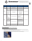
Table 1: Description of Wire Harnesses
Type of Wire
Harness
Indoor Unit Models
Connector to Indoor Unit Control
Board
Connector to Thermistor
Connector to
Control Box
M2 Wire
Harness
MS MSZ/Y
MFZ
2 pin, female connector (with black
heat shrink) to CN111
2 pin, male connector to:
RT11 (Room Temp. Thermistor)
2 pin, male connector
P Wire
Harness
PKA PCA
PEA(D)
SEZ
2 pin, female connector to CN20
2 pin, male connector to:
TH1 (Room Temp. Thermistor)
2 pin, male connector
PKFY-P**NBMU-E
PLFY-P**NCMU-E
PMFY-P**NBMU-E
PVFY-P**E00A
PEFY-P**NMHU-E
2 pin, female connector to CN20,
CN21 or CN29
2 pin, male connector to:
TH1 (Room Temp. Thermistor) or
TH22 (Pipe Temp.
Thermistor/Liquid) or
TH23 (Pipe Temp
Thermistor/Gas)
M1 Wire
Harness
PKA
PCA
PEA(D)
SEZ
PKFY-P**NH/KMU-E
PLFY-P**NBMU-E
PCFY-P**NKMU-E
PEFY-P**NMS/AU-E
4 pin, female connector to CN44
4 pin, male connector to
TH2 (Pipe Temp.
Thermistor/Liquid) and
TH5 (Pipe Temp. Thermistor/Gas)
2 pin, male connector
MS
4 pin, female connector to CN112
4 pin, male connector to
RT12 (Coil Temp. Thermistor)
MSZ/Y
4 pin, male connector to
RT12 (Coil Temp. Thermistor –
Main) and
RT13 (Coil Temp. Thermistor –
Sub)
MFZ 4 pin, female connector to CN113
4 pin, male connector to
RT15 (Coil Temp. Thermistor)
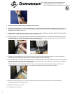
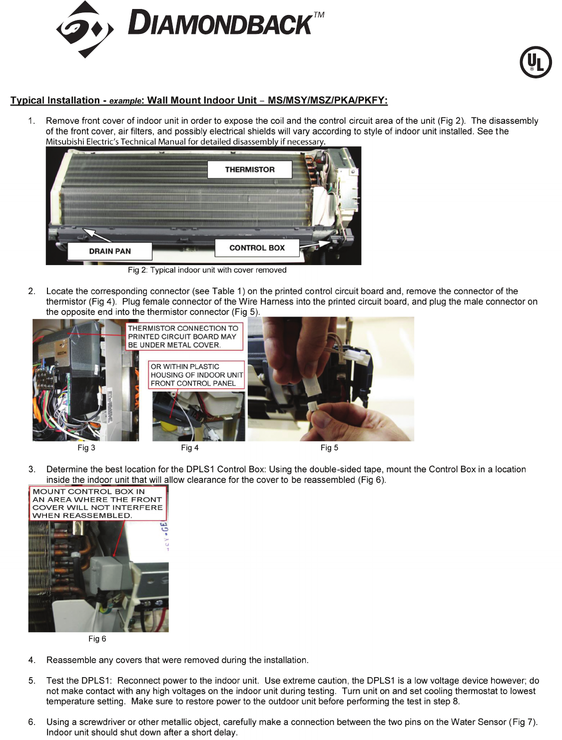
INSTALLATION OF DPLS1 Drain Pan Level Sensor/Control:
(To ensure proper performance of product, instructions must be followed.)
1. Disconnect (and lock-out, if required) all power to the Mr. Slim or CITY MULTI Indoor Unit at the Disconnect Switch (if
installed) or at the main disconnect panel serving the indoor and/or outdoor unit.
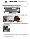
2. Connect DPLS1 Splice Connector to the selected mating Wire Harness Connector – see wiring harness selection above.
Connect the Control Box’s Splice C onnector to the mating connector on the Wire Harness (Fig 1).
Fig 1
4F Wire
Harness
All indoor units, with
CN-4F Connector on
4 pin terminate to CN-4F if available -
CN-4F is used for other function use
If CN-4F not available
2 pin, male connector
Control Board Thermistor Connection Method